| Home | Ian Bower | Building Statistics | Thesis Abstract | Technical Assignments | Thesis Proposal | Presentation | Final Report | Reflection | E-Studio |
|---|
News Update |
|
Date |
Announcements |
4/24/13 |
CPEP Complete |
4/15/13 |
|
4/8/13 |
|
4/3/13 |
|
1/14/13 |
|
1/10/13 |
|
12/14/2012 |
|
| 11/12/2012 | Tech 3 Posted |
| 10/22/2012 | Abstract Posted |
| 10/02/2012 | Tech 2 Posted |
| 9/22/2012 | Tech 1 Posted |
| 9/17/2012 | Building Statistics 1 Posted |
| 9/10/2012 | Student Bio Sketch Posted |
| 8/31/2012 | Home Page Posted |
| 8/31/2012 | Building Statistics 1 Complete |
| 8/30/2012 | Owner Permission Obtained |
| 8/05/2012 | Full Menu Functionality |
| 5/09/2012 | Project Documentation Obtained |
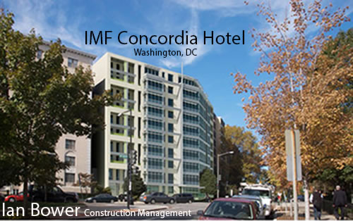
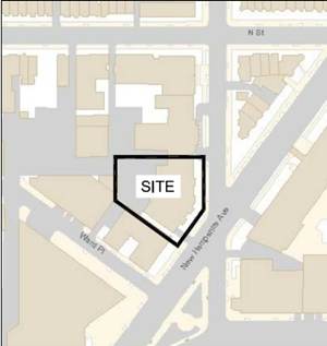
Building name-The Concordia Location and site-Washington, D.C. The specific address cannot be used
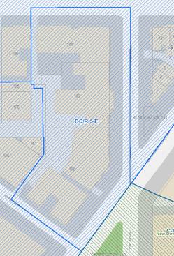
Building occupant name Occupants for the extended stay Hotel will include visitors for the International Monetary Fund Training Institute, the World Bank and other companies. The owners will be ARAMARK Harrison Lodging. (http://www.bonstra.com/) and (http://www.theconcordia.com/about.php) Occupancy or function types Based on the fact that this is a hotel that offers extended stay this structure would not be considered an apartment building. This structure will be defined as a hotel and therefore be classified in the R-2 residential based on a transient occupancy type. (http://afcity.org/LinkClick.aspx?fileticket=dg13SzQ8bSk%3D&tabid=286&mid=579) S-2 parking garage (incidental use) Size (total square feet) This remarkably redesigned hotel will have a total square foot of 96,200. (http://www.bonstra.com/) Number of stories above grade/total levels The Concordia consists of 10 stories with a single basement and parking garage below grade. Primary project team including Contractor-cannot be named ARAMARK Harrison Lodging (http://www.theconcordia.com/about.php) CM-Turner Construction Company Civil engineer-Wiles Mensch Corporation (http://www.wilesmensch.com/) Interior architect-Baskervill (http://baskervill.com/) Architects-Bonstra Haresign Architects LLP (http://www.bonstra.com/) Mechanical, electrical and plumbing engineer-WSP Flack + Kurtz (http://www.wspgroup.com/en/Welcome-to-WSP-Flack--Kurtz/WSP-Flack-Kurtz/) Structural engineers-SK&A (http://www.skaengineers.com/home.asp) Landscape architect-Landscape Architecture Bureau (http://www.labindc.com/) Specifications consultant-Bethel Specifications Consulting (unable to locate website) Lighting design-MAG Lighting Design, LLC (http://www.mag-lightingdesign.com/) Acoustic Engineering-Polysonics Acoustics & Technology Consultants (http://www.polysonics-corp.com/) Vertical transportation-Lerch-Bates, Inc. (http://www.lerchbates.com/) Cost Consultant-Faithful + Gould (http://www.fgould.com/) Dates of construction (start-finish) November 2011-December 2012 Actual cost information $23,000,000 overall project cost Project delivery method Lump Sum Contract type Architecture Architecture (Design and functional components)-The Concordia is a 10-story plus cellar and underground parking garage extended stay facility with two main structures connected at the ground floor. While the entire building is composed of 178 rooms the bond building has 78 while the Concordia houses the other 100. It was designed in by Berla & Able. Major national model codes (IBC 2003, BOCA 1999) IBC 2006/DCMR 12A-2008 IBC 2006/DCMR 12E-2008 IPC 2006/DCMR12F-2008 NFPA NEC 2005/DCMR 12C-2008 IFC 2006/DCMR 12H-2008 IFGC 2006/12I-2008 IEBC 2006/DCMR 12J-2008 ANSI 117.1-2003/DCMR 12A Chapter 11 DCMR Title 11-zoning regulations District of Columbia Environmental Policy Act of 1989 Green Building Act of 2006 Zoning DC/R-5-E Overlay (http://maps.dcoz.dc.gov/#)
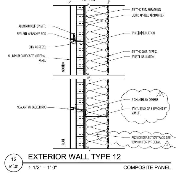
Historical requirements of building or historical district where built. In 1965 the IMF Concordia was designed by Berla & Able. The building is neither in a historical district nor are there historical requirements for salvaging portions of the building or the building’s façade. Building enclosure Building facadesExterior wall type # 12 consists of 6” Batt insulation, 5/8” thick exterior sheathing, liquid applied air barrier, 2” rigid insulation, aluminum clip, sealant with backer rod and shims where required. The last layer to make up the wall is the aluminum composite material panel.
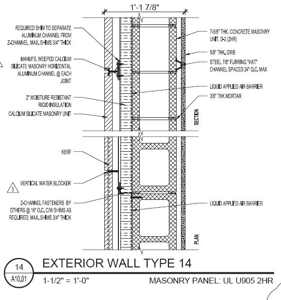
Exterior wall type # 14 will be composed of 7-5/8” thick Concrete Masonry Units (CMU) with a liquid applied air barrier, Z-channel fasteners @ 16” O.C., 2” moisture resistant rigid insulation, required shim to separate aluminum channel from Z-channel, max shims ¾” thick, weeped calcium silicate channel, and finally a calcium silicate masonry unit.
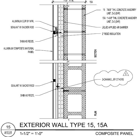
Exterior wall type # 15 has 7-5/8” thick CMUs while wall type 15a has 11-5/8” thick CMUs. They have essentially matching components which include liquid applied air barriers, 2” rigid insulation, aluminum clip, sealant with backer rod and shims where required. The last layer to make up the wall is the aluminum composite material panel.
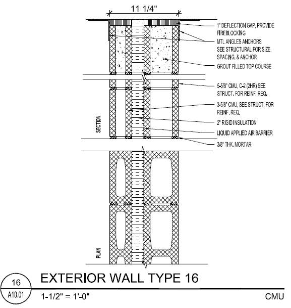
Exterior wall type # 16 has 5-5/8” CMUs, liquid applied air barrier, 2” rigid insulation, 3-5/8” CMU, and lastly metal anchors.
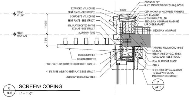
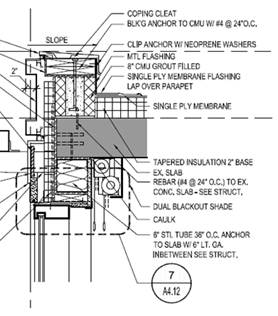
The building façade has an Aluminum Trellis’ and aluminum panels with aluminum coping.
Roofing The roof is composed of tapered insulation with a 2” base and a single ply membrane both of which rest on the existing slab.
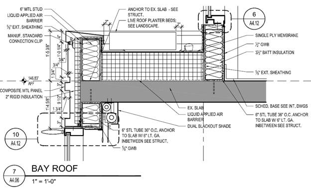
The live planter roofing will consist of a liquid applied air barrier installed on top of the existing slab which will be followed by much thicker tapered insulation, a single ply membrane and lastly live roof planter beds.
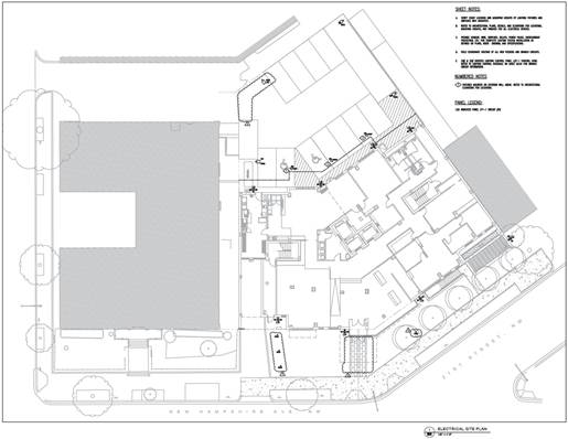
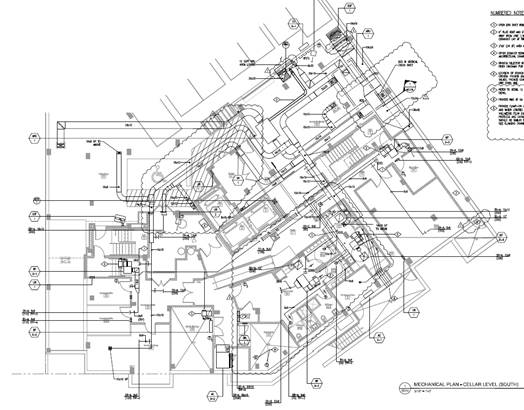
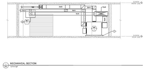
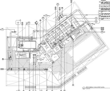
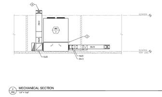
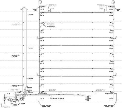
Sustainability features Due to the outdated inefficient systems which were installed when the building was completed this renovation will gut and renovate all the major MEP systems. The renovation of the IMF Concordia is planning to achieve a LEED Gold certification. The goal of achieving this certification will be dependent on the many systems of the structure coming together to produce an efficient building. Plumbing The renovation of The Concordia’s will include the installation of Domestic Booster Pumps in order to help produce a more efficient, energy saving plumbing system. Electrical Turner’s renovation of the Concordia will include the installation of LED down lights in many of the corridors as well as many other LED fixtures throughout the building. Mechanical This renovation will make the building’s mechanical system more efficient by installing 100% outside air packaged energy recovery air handling units and 100% outside air makeup air units The mechanical system will be improved drastically by installing Variable Refrigerant Volume (VRV) systems. (http://www.mechanicalservicesfiji.com/vrv_aircon.html)
Roofing The bay roof will have live roof planter beds in order to help reduce the heat island effect as well as storm water runoff.
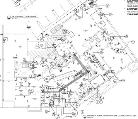
Electrical/Lighting
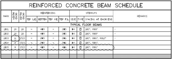
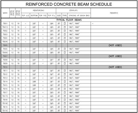
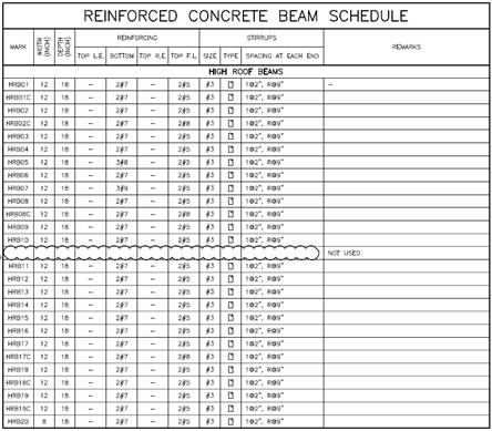
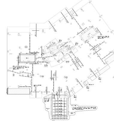
First Floor Beam Schedule (New Construction) Even & Odd Floor (Floors 2, 3, 4, 5, 6, 7, 8, 9, 10) Beam Schedule (New Construction)
Transportation The existing elevator core had only two elevators, one freight elevator and one passenger elevator. The existing core was removed to make room for the new elevator core which would have three elevators. The Concordia Hotel has two passenger elevators and one freight elevator. The existing stair well/elevator core has been demolished and two new stairwells have been installed. This installation required the strengthening of key slabs through the construction of several beams, columns and CFRP. The new construction of the two stairwells will be located on either side of the structure. Telecommunications Due to the structure being an extended stay type hotel there will be security rooms and security systems installed to limit the building access only to approved hotel guests. The project will also have key audio visual/information technology equipment to provide guests with the capabilities that they desire. |
|---|

Contact Me |
| Note: While great efforts have been taken to provide accurate and completeinformation on the pages CPEP, please be aware that the information contained herewith is considered a work-in-progress for this thesis project. Modifications and changes related to the original building designs and construction methodologies for this senior thesis project are solely the interpretation of Ian Bower. Changes and discrepancies in no way imply that the original design contained errors or was flawed. differing assumptions, code references, requirements, and methodologies have been incorporated into this thesis project; therefore, investigation results may vary from the original design. |
This page was last updated on 12/03/2012, by Ian Bower and is hosted by the AE Department 2012 |