Analysis 1 (Foundation
Redesign)
In order to eliminate the potential collapsing of drilled caisson holes without the use of time consuming prevention methods, a different type of foundation was analyzed. The alternative system is an auger cast-in-place (ACIP) pile foundation (see Figure 8 Below). This type of foundation system proves to be more efficient than caissons for this project for a number of reasons. ACIP pile foundation systems differ from caisson foundation systems in their overall composition. They are similar in shape but smaller in diameter.
In the ACIP pile system, concrete is placed in the drilled
hole as the drill bit is removed, eliminating the potential for the hole to
“cave in” due to saturated soil. The concrete is poured under pressure in this
system. This means of concrete placement is similar to that of the tremie, or slurry method. Using this technique of placing
concrete eliminates the need to use steel casing and therefore time and
material can be saved. After the concrete piles are poured and while it is
still wet, the steel reinforcing is placed as opposed to caisson construction
where the reinforcing is placed before the concrete is poured. ACIP piles are
smaller than caissons in general, as were the ones used for this analysis. The
ACIP piles used in the design of this alternate system are mostly all the same
size diameter, which is typical. In the design for this alternate foundation
scheme, the piles are all two (2) feet in diameter. Since these drilled shafts are much smaller
in diameter than that those of the original foundation, they must be placed in
groups in order to reach the same structural capability. In place of one
caisson, two or more piles are needed to make up for the strength. However,
since the piles have no steel casing and they are poured under pressure, their
capacities are greatly increased because their average unit surface friction is
much greater. The average coefficient of earth pressure on the pile shaft is
denoted by the letter “K” in the bearing capacity determination (Appendix A).
For a shaft encased in steel lining, the value of “K” is 1.1. For concrete, the
value is about 36% more at 1.5. Given a steel 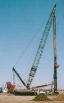 lined
caisson and an auger cast pile of the same dimension, this is the only factor
that varies between the two for one given site condition. It is for this reason
that the surface friction, and therefore the total bearing capacity of an auger
cast pile is at least 36% more than that of a steel lined caisson in the right
soil conditions. In this situation, smaller diameter shafts for ACIP piles can
possess the same capacity as larger diameters used in caissons in some cases.
Obtaining the surface friction using 1.5 for “K” is conservative in this
analysis because this is the number for somewhat smooth concrete surfaces. It
does not take into consideration the much rougher surfaces that auger cast
piling tends to produce.
lined
caisson and an auger cast pile of the same dimension, this is the only factor
that varies between the two for one given site condition. It is for this reason
that the surface friction, and therefore the total bearing capacity of an auger
cast pile is at least 36% more than that of a steel lined caisson in the right
soil conditions. In this situation, smaller diameter shafts for ACIP piles can
possess the same capacity as larger diameters used in caissons in some cases.
Obtaining the surface friction using 1.5 for “K” is conservative in this
analysis because this is the number for somewhat smooth concrete surfaces. It
does not take into consideration the much rougher surfaces that auger cast
piling tends to produce.
Using the estimated bearing capacity of a single pile, it
was determined how many piles would be needed to meet the required strength to
replace each caisson based on the intended building column loads of about 300
to 500 kips. For a 24 inch diameter and
average of 50 feet deep ACIP pile the estimated bearing capacity is 200 Kips as
determined in appendix A. This number is conservative because of the use of
conservative values for soil cohesion factors (C), internal angle of friction
(ø), soil unit weight (γ), and the average coefficient of earth pressure
(K). However, the actual bearing capacity can only be achieved through testing
methods after the piles are installed. The actual bearing capacity is to a
large extent influenced by the equipment used and the experience of the operator.
Once the number of piles was determined then the
determination of their placement and the dimensions of pile caps were figured
out. These pile caps are used to transmit the column loads of the building to a
group or cluster of piles (Cernica, 185). In addition
to the intended column loads, the load that the pile caps inflict upon  the
piles must be taken into consideration. This was determined simply based on the
volume of the caps and the average weight of concrete. Based on the intended
column loads and the number of piles in each cluster, four different
configurations of pile placement were used in the analysis to replace the
bearing capacity requirements of the original caissons (Figure 5). The pile
the
piles must be taken into consideration. This was determined simply based on the
volume of the caps and the average weight of concrete. Based on the intended
column loads and the number of piles in each cluster, four different
configurations of pile placement were used in the analysis to replace the
bearing capacity requirements of the original caissons (Figure 5). The pile
caps designed for this system are 49 inches deep and their areas are sized based on the number of piles and their placement. The areas of the pile caps were determined using general methods of design. The caps are to extend at least one diameter in width beyond the pile. The depth of the pile caps was obtained based on the maximum that is generally used and was applied to each one regardless of their intended bearing capacity requirements. The reason that the maximum size was used was for simplicity. This eliminates the need to determine punching shear that may occur in a pile cap with a smaller thickness. Determining the components necessary for the alternative ACIP pile system was the first step. After this information is known, the cost and duration of construction can be estimated using these figures.
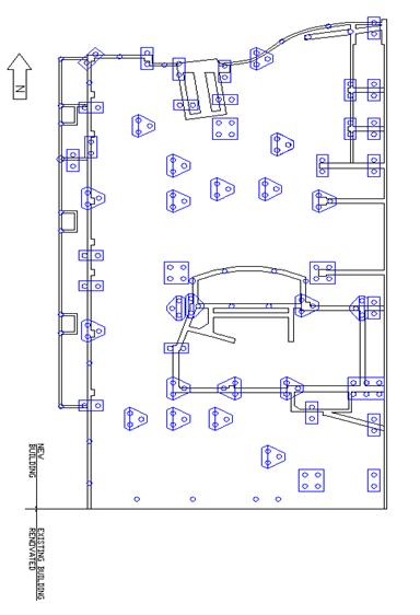
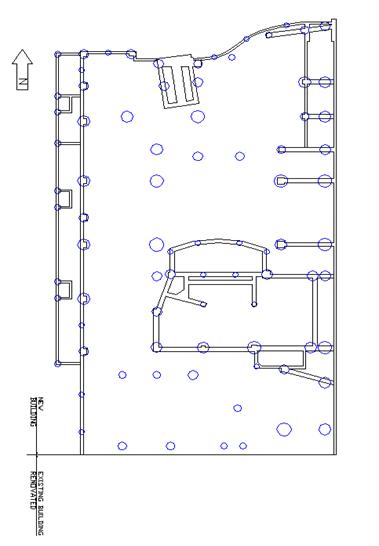
Figure 7 (Original Caisson Foundation Layout) Figure 8 (Alternate ACP layout)
Analysis 2 ( Foundation
Constructability, Cost, and Duration Impacts)
Analyzing the costs of each system it was determined that there is some discrepancy in the results estimated by using different methods. Where one method showed that there is very little difference in material costs between the caisson foundations system and the ACIP pile foundation system, another showed that there is. ICE 2000 Estimating showed no significant difference in costs (See appendix B). At this point it was figured that where steel casing is eliminated for caissons, pile caps basically offset that savings in the ACIP pile system. It was also figured that concrete and steel reinforcing were similar in cost for each of the two systems. According to an estimate completed using Means Cost Guides there was a significant difference in the overall costs of the two systems. After discussing these results with experienced consultants, it was determined that Means would be the better method of estimating the foundation systems costs. Referencing different contractors in the area also showed there is likely not much of a significance cost difference between the two foundation systems in terms of materials but a definite cost reduction in using ACIP piles due to a savings in time. In the results obtained using ICE 2000, each of the two foundation systems came out to be about $500,000. This number is very close to what was obtained for ACIP piles in Means, but very far off from that of caissons. The results that were obtained from Means are shown below in Figure 9. These results illustrate that caissons are about $455,000 more expensive than ACIP piles for the CAPA project. Based on predictions from researching the topic as well as consulting with experienced professors and contractors, this number turns out to be more realistic.
There is undoubtedly a reduction in time in the construction of ACIP piles compared to caissons. Roughly two (2) caissons can be installed verses about ten (10) piles in one work day. It would take about four months to finish the installation of caissons where piles can be constructed in about three months based on their constructability methods. In other words, ACIP piles could be installed about a month faster than caissons. The construction of pile caps is a fairly easy and quick process that only adds a little time to the overall construction of the system. Figure 10 below shows a more detailed time estimate for these systems. Furthermore, different methods for inspecting the holes are used which make the process faster. In the case of caisson construction, many times each caisson must be physically inspected once the hole is drilled. An inspector must actually enter the hole to inspect the actual conditions. In this case there are stringent safety requirements which need to take place before someone can enter the hole. Applying these safety requirements takes up valuable time in some circumstances. ACIP pile systems use different methods and technology for inspection. These quality control methods include simple manual techniques as well as computerized installation monitoring equipment and sonic integrity testing methods (Brettman p. 458). Though the manual testing of these systems is inefficient, the more modern computerized methods are fairly easy to perform and are reliable. The Pulse Echo Methods is a non-destructive method of testing which determines if any deficiencies are present in the piles simply using a hammer and an accelerometer. Sometimes more stringent testing is required for certain projects, but this method is all that is needed in others. The foundation being a critical activity on this project means that finishing it sooner would allow for other work to begin sooner, in turn, accelerating the entire project. A comparison of two project schedules, one using caissons, and one using ACIP piles, are used in appendix C to illustrate this.

Figure 9 (Means Foundation System Cost Analysis
|
Foundation
Construction Duration |
|||
|
|
|
|
|
|
Caisson |
Daily Output |
Total V.L.F. |
Days to |
|
Diameter |
(V.L.F) |
per Caisson Size |
Complete |
|
30" |
95 |
102 |
1.1 |
|
36" |
70 |
290 |
4.1 |
|
42" |
68 |
175 |
2.6 |
|
48" |
65 |
282 |
4.3 |
|
54" |
55 |
914 |
16.6 |
|
60" |
48 |
262 |
5.5 |
|
66" |
45 |
774 |
17.2 |
|
72" |
43 |
382 |
8.9 |
|
78" |
40 |
107 |
2.7 |
|
Total |
|
|
63.0 |
|
|
|
|
|
|
Pile |
Daily Output |
Total V.L.F. |
Days to |
|
Diameter |
(V.L.F) |
per Pile Size |
Complete |
|
24" |
220 |
9164.75 |
41.7 |
|
36" |
125 |
161 |
1.3 |
|
Total |
|
|
42.9 |
|
|
|
|
|
|
Pile Caps |
|
|
|
|
|
|
|
|
|
|
Caisson Construction
Time |
63.0 |
|
|
|
ACIP Pile
Construction Time |
43.0 |
|
|
|
Difference |
|
20 Days |
|
|
|
|
|
|
This
information was obtained using Means Cost Guides |
|||
Figure 10 (Foundation Duration Estimate)