
CIMLAB Floor Plan
-Click on machines to see specifications-
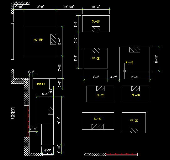
Arrangement of Work Cells
|
Storage Work Cell
|
Work Cell 1
|
Work Cell 2
|
Work Cell 3
|
|
Material Transporter/Handler
|
Material Handler
|
||
|
Potential Material
Handlers
|
|
|
Storage Work Cell
|
Work Cell 3
|
|
ABB IRB-2400L
|
|
The layout for the Penn State CIM Lab was evaluated according to the following criteria: efficient use of allocated space, accessibility to equipment for normal usage and maintenance, material handling and transport requirements, and visual appeal.
Every effort was made to configure each cell such that it would occupy two bays with minimal overlap. In terms of efficient use of space, each design was penalized for wasted or dead space and for intrusion upon neighboring bays. In addition, wherever possible a three-foot service area was provided around each machine for side-door access and maintenance. This area may overlap between machines without penalty; however, penalties were levied for adjacencies that would not allow for ease of passage for persons maintaining the cells.
Several assumptions were made in the course of planning the layout of the Leonhard CIM Lab. First, in terms of the dedicated and non-dedicated CIM cells, the most flexible equipment (those with multiple axis machining capabilities and those with pallet exchangers and bar feeding mechanisms) was allocated to the dedicated cell or cells. Second for future planning purposes, allowances for both path and porting was provided for a four-foot wide Automated Guided Vehicle (AGV).
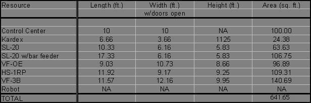
Square Footage Requirements
The following table (Table 1- Space Requirements ) contains the dimension specifications for the equipment included in the Leonhard CIM Laboratory. The square footage requirements indicated in the table only represents the absolute minimum space required by the resources to be included in the CIM cells.
Table 1. Space Requirements