

ARENA Simulation
Table of Contents
Introduction
Implementation
Experiment frame
Model frame
Animation
Introduction
The ARENA graphics simulation software is a complete and flexible modeling environment combined with an easy-to-use graphical user interface. It is designed for building computer models that accurately represent real world applications. ARENA integrates all simulation-related functions like animation, input data analysis, model verification, and output analysis--into a single simulation modeling environment. The real-time package is capable of sending messages to third-party controller software for real-time control of automated systems. In real-time mode the simulation clock operates just like a real-time clock.
In this project, ARENA RT (real-time) is used to control the whole system of eight equipment level controllers through a master controller called Big-executer (Big-E). Basically, the simulation model reads the order entries and the corresponding master production schedule from the manufacturing database and sends the required messages to Big-E. After sending the message, the simulation model waits for the verification message from Big-E telling that the command has been executed properly and the system is ready for the next message. Consequently, ARENA simulation sends a sequence of messages throughout the processing of a shop order, which direct the part inside the physical system. Upon the completion of an order, the simulation model updates the order entry table in the manufacturing database verifying that the order has been completed and ready for shipment.
Implementation
The simulation model is the main decision maker in the system. It checks for the orders in the manufacturing database and sends the necessary messages to shop floor controller (Big-E) for execution. The connection between the simulation model and the database is established through the use of a custom dynamic link library (MSUSERC.DLL) that has been previously developed. This file is the link between the database and the simulation model. Before running the simulation model, the dynamic link library has be defined in the ARENA run setup.
When the simulation model is ran, it first connects to the router software in order to communicate the shop floor controller, Big-E. The communication is established over the Local Area Network. After connecting to the router software, the model asks for the name of the manufacturing database. As explained in the database section, the manufacturing database should be previously defined in the ODBC Data Sources as a system data source. After the database file is selected the simulation model starts running. In the animation view, the busy resources can be tracked to understand the part routings. The animation view also includes the counters for number of parts present in the system and the number of parts that have been completed from the current work order.
Experiment Frame
Experiment frame includes the declarations of the ARENA simulation model components such as attributes, variables, queues, resources etc. All the messages sent to the execution system are defined in the experiment frame.
The messages are defined with nicknames in the simulation model since the message structure is long. Each message has its own parameters. The parameters are actually the attributes in the simulation model and the values of the parameters are read from the manufacturing database and assigned to the attributes by the DLL file. There is a single attribute, sm_Execute, which tells ARENA if the system is in execution mode or not. In the execution mode, ARENA actually sends the messages to the router software. In the emulation mode, as opposed to the execution mode, ARENA does not send the messages and just emulates the run. If sm_Execute has a value other than zero, then the system will be in execution mode.
Model Frame
Model frame is composed of seven distinct modules of SIMAN code. Each of these modules contains the logic for a specific part of the automated manufacturing system in the FAME Lab. These modules are as follows:
1. Check for new order in the manufacturing database
2. Get information on part type and make the decision on part release
3. Departure from Workstation 2 (remove part from KARDEX AS/RS)
4. Workstation 3 HAAS HS1RP with pallet exchanger
5. Workstation 4 (HAAS SL20, VF-OE, VF-3 and human material handler)
6. Workstation 1 (HAAS SL20 with bar-feeder)
7. Return finished product to Workstation 2 (arrive into KARDEX AS/RS) and dispose the entity
Module 1. New order checking

This module creates a dummy entity every 30 seconds to initiate an event for user coded DLL file to check for a new order entry in the manufacturing database. Event 1 calls a function in the DLL file to check for a new order entry in the manufacturing database and if there is one reads the order size and assigns it to an internal attribute in the simulation model.
Module 2. Get information on part type and make the decision on part release
This module creates the entities that represent the work order in the manufacturing system. The scan block controls the release of the entities into the system by checking the status of the HAAS SL20 with bar feeder and the material transfer operator, since these two members of the system are required to be idle for the part to progress in the system at the beginning. Since the system does not have a logic for deadlock detection and complex resource scheduling, for now the system can be utilized only as a flow shop if more than one part is permitted inside the system. This means that a work order cannot have different part types those require different routings in the system simultaneously. When a work order is decided to be released into the system, the initiating message of part_enter is sent to the Big-E which creates a new object in the execution system representing the part in the manufacturing system. The new part has two possible routings, it can either start as a bar in the bar feeder or it can start as a raw material stored in the KARDEX AS/RS.
Module 3. Departure from Workstation 2 (remove part from KARDEX AS/RS)
After the part enters the system from module2 it comes to this module if it is a raw part stored in the KARDEX AS/RS. The part is first assigned to the material transfer operator and then removed from the KARDEX by the operator. The next step is to transfer the part to its next machine in the routing. The route block direct the transfer operator to the next workstation in the routing of the part by checking the internal attribute port_loc. The event 3 blocks in all of the modules reads a line from the routing summary of the part
Module 4. Workstation 3 HAAS HS1RP with pallet exchanger
This module governs the processing of a part in HAAS HS1RP with pallet exchanger. The material transfer operator first places the part in the machine and then the tombstone is rotated to orient the part for machining operation. After the part is processed, the tombstone is rotated and the part is unloaded from the machine. In case of another process on this machine the choose block redirects the entity to the event block after which the process message is sent to the system.
Module 5. Workstation 4 (HAAS SL20, VF-OE, VF-3 and human material handler)
Third module is the largest of the seven. The reason is it includes three machines and the material handler inside workstation four. When a part enters workstation four, it will be put into the buffer inside workstation four. Then the material handler inside the workstation picks the part from the buffer and places in the machine that is the next in the routing of that specific part. The routing is being read from the database by the event block as in the previous modules. Once the part is in one the machines, the part program is loaded and the part is being processed. When the processing is done, the part is removed from that machine and placed either in the buffer or placed in another machine depending on its routing. When the part is placed in the buffer, the material transfer operator picks up the part and transfers to the next station in the routing.
Module 6. Workstation 1 (HAAS SL20 with bar-feeder)
Module six is very similar to module four. The machine is HAAS SL20 with bar feeder instead of HAAS HS1RP. In this module there is no rotation messages and no reprocessing since this lathe is not used for more than one operation.
Module 7. Return finished product to Workstation 2 (arrive into KARDEX AS/RS) and dispose the entity
When the part is completed, the material transfer operator transfers it back to the KARDEX AS/RS. After the part is placed in KARDEX, the number of parts in the system is decreased by one, and the number of completed parts is increased by one. The event block at the end triggers the function in the DLL file that updates the manufacturing database. Every time a part is completed from an ongoing order, the number of unfinished parts in the database is decreased by one by the DLL file. When all the parts are completed the work order entry is erased from the database. At the very end the entity is disposed from the simulation.
Animation
ARENA has the capability of animating the simulation model. When simulation is used for control of the manufacturing systems, animation provides a small-scale visual representation of the on-going activities in the manufacturing system. Therefore, it is very useful for monitoring of the physical system and real-time statistical analysis.
The system in this project is animated in ARENA. The status of the resources can be seen in the animation during the run and the parts can be tracked looking at the resources. The animation can be improved by assigning images to parts that will provide the ease in following the parts during a production run.
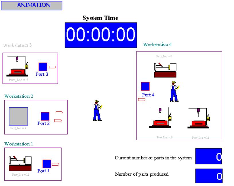
The human figures represents the operators who are responsible for handling and transferring the parts in the system. The human operator in the middle have permission for transferring the among the workstations whereas the material handler inside workstation four is only permitted to handle the parts inside workstation four. Therefore, the operator in the middle has more flexibility than the one in the workstation and he is called MTMH denoting material transporter and handler.
The clock at the top operates as a real-time clock during the control run and the counters at the bottom-right shows the number of parts present in the system and the number of parts completed from the current work order. Each port denotes the entry and exit location for that workstation. When any of the resources (either the handlers or the machines) becomes busy, a busy indicator appears on that resource.