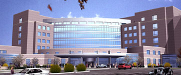
Christiana Hosptial 2010 Project
Occupant: Christiana Care Health System
Building Funtion: Hospital
Total Project Cost: $126 Million
Structural Steel/Misc. Metals Cost: $2,897,875
Concrete Cost: $9,320,230
Size (square feet): 299,000
Number of Stories: 9 stories - includes 1 below grade
Project Delivery Method: Design-Bid-Build
Project Duration: E Tower Structure - 9/1/04 through 2/15/05
------------------ E Tower Penthouse Steel - 2/16/05 through 3/1/05
------------------------- Conference Center - 1/17/05 through 3/11/05
Architect: Wilmot Sanz
Civil Engineers: VanDemark & Lynch, Inc.
MEP Engineers: RMF Engineering, Inc.
Structural Engineer: Cagley & Associates
Architecture: The structure is essentially L-shaped having a center tower joining the two legs. This design brings a contemporary feel to the medical campus with its unique shape, large spans of glass, and brick cladding.
Roof: Roofing membrane on tapered insulation
Major National Model Codes: International Building Code - 2000
Structural:
The building is mainly composed of structurally reinforced concrete with a stand alone adjacent steel framed conference wing. The concrete portion of the building stands 8 stories with one level underground and a penthouse roof. The structure contains varying spans which are created using a typical 9½ inch thick two-way flat slab with 5½ inch drops or shear caps. This slab transfers load to 24 inch square columns which in turn take the load down to a mat foundation. To prevent rotation and lateral displacement due to wind or seismic loading shear walls are strategically placed perpendicular to the buildings perimeter.
The conference wing is a 3 story structural steel frame with a majority of beams having pinned connections (figure 7 of Appendix) and spanning around 30 feet. In the center of this area is a larger span of over 60 feet. The buildings loads are transferred to the beams using a 3¼ inch, light weight concrete, structural slab over a 2 inch deep by 18 gage galvanized composite metal deck creating a total slab thickness of 5¼ inches. The load in the beams is transferred to steel girders which are attached using a pinned connection to W-shaped columns. These columns continue down to 4000 psi concrete spread footings. The wind and seismic loading in this area is distributed using concentrically braced frames. |
Mechanical:
The Christiana Hospital Project’s air quality and temperature is maintained using eight (8) separate air handling units with variable volume air terminal reheat units. These air handling units have the capability of moving air at rates ranging from 22,800 – 32,000 CFM (cubic feet per minute). To heat or cool the air in the building, supply air passes over coils containing either steam or chilled water which is supplied to the building by an outside source. Because this facility is a hospital the areas which the air handlers distribute and collect air from are separated. The clinical areas receive air from four (4) air handlers located on the eighth floor which contain special filters designed for hospital applications. The remainder of the building receives its air from the four (4) other air handlers located on the roof of the conference wing and in the basement of the main building. |
Electrical:
This project makes use of a secondary selective distribution system which allows for improved reliability. Two sets of 35 KV primary feeders service the building. Prior to entering the building these feeders are both stepped down to a primary utilization voltage of 480/277. Once inside, the power runs through two tie-breaker switchgears with the capability of rerouting power without interruption if need be. The majority of the building’s mechanical equipment and lighting loads run on this voltage. For use with outlets and certain pieces of mechanical equipment seven (7) step-down transformers are used to create a voltage of 208/120. In the event of an emergency a 1500 KW emergency generator serves the building through a 5 KV emergency switchgear. The power created using this generator is first stepped down to 480/277 volts by a 1500 KVA pad mounted transformer for use with the life safety loads of the building.
|
Lighting:
As you enter the building through the main lobby area the lighting is primarily metal halides. Throughout the rest of the building’s interior lighting is accomplished using a blend of linear fluorescents, fluorescents, and halogen lights and fixtures with LED (light-emitting diode) accents in select locations. Around the exterior of the building HPS (high pressure sodium) and metal halide pole lamps are used while the main entrance canopy is lit using recessed fluorescent lighting.
|