Building Statistics
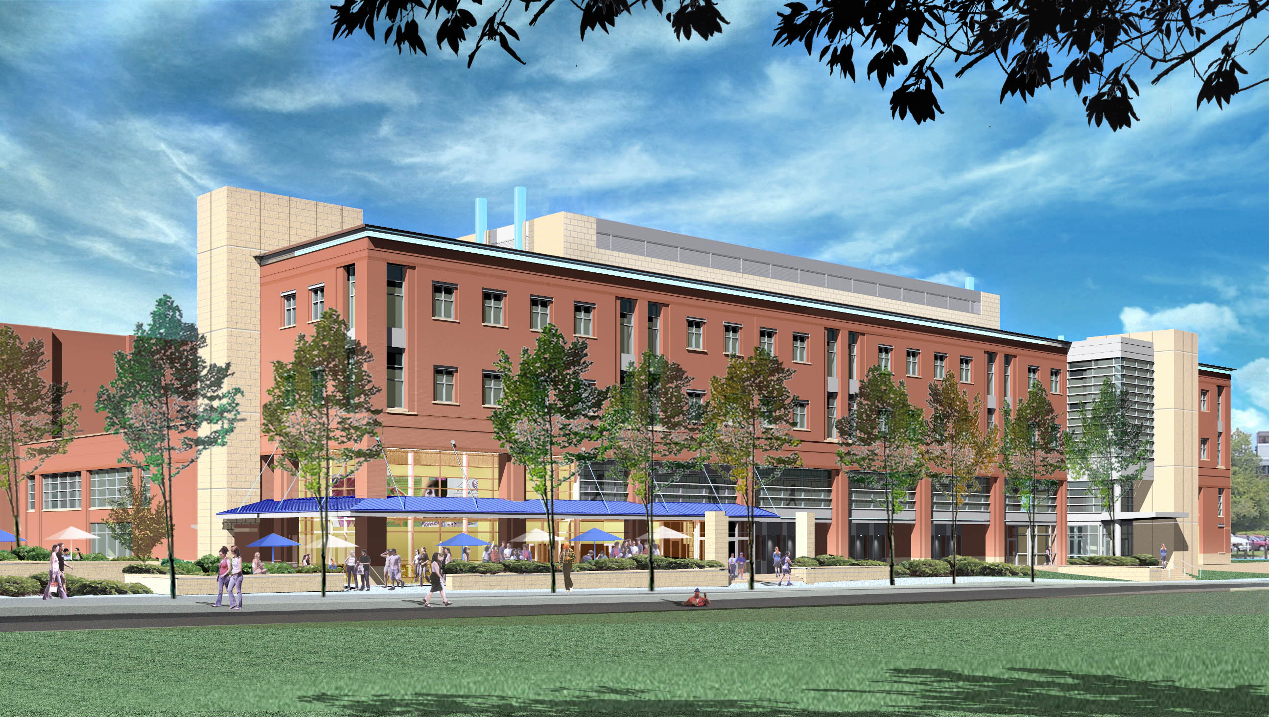
The New Food Science Building
At Penn State University
Were real-world science leads to exciting new careers!
BUILDING STATISTICS
General Building Statistics:
- Building Name: Food Science Building
- Location and Site: 322 East Park Ave., State College, PA 16803
- Occupancy or Function Type: The Department of Food Sciences and the new PSU Creamery Building.
- Primary Occupancy: Food processing, production, and manufacturing.
- Secondary Occupancy: Creamery laboratory and sales area.
- Additional Occupancy: Classrooms and laboratories to support research and teaching programs.
- Total Square Feet: 122,000 Sq. Ft
- Future Square Feet: 17,600 Sq. Ft.
Building Occupant Name: The Pennsylvania State University
? Owner: The Pennsylvania State University
Website: www.psu.edu
? Architect: IKM Incorporated
Website: www.ikminc.com
? Structural, Civil, MEP, and Fire Protection Engineers: H.F. Lenz Co.
Website: www.hflenz.com
? Food Processing Engineers: Food Engineering, Inc.
Website: www.foodenginc.com
? General Contractor/ Construction Manager: Gilbane Building Co.
Website: www.gilbaneco.com
• Dates of Construction (Start –Finish): November 2004 – September 2006
• Cost:
? Construction Cost: $33 million
? Total Building Cost: $43 million
• Project Delivery Method: Design–Bid–Build
Building System Information:
History:
The Food Science Building’s primary use will serve as the new home for the well-known PSU Creamery. It will be the fourth home that the PSU Creamery has had since its existence dating back to 1889. In 1889 the Creamery began from a $7,000 dollar state appropriation as a one-story structure that contained everything necessary to enhance the Department of Agriculture’s instruction and research in dairying. In 1904 the Creamery moved to Patterson Building and in 1932 it once again moved to Borland Laboratory where it resides today. It was determined that new construction is more efficient than a renovation and addition to Borland Laboratory. The move into their new facility, a block down Curtain Rd., will occur during the summer of 2006.
Architecture:
The building architecture was designed to make a statement about the importance of the food processing and manufacturing sector. Visibility is high for the Creamery Processing/Manufacturing area and also for the Pilot Plant, emphasizing the importance of these areas to the departmental academic programs. The idea of research was therefore designed to include faculty office space, laboratory space, space for informal interactions, and joint-use research space. The idea was to encourage collaboration among faculty members, especially within groups and among graduate students.
The nature of the project is unusual with respect to the fraction of the
total area that is on the first floor to accommodate the Creamery Processing/Manufacturing
facility, salesroom, and pilot plant. Higher-than-normal ceilings and load
bearing flooring were used to accommodate this specialized equipment. Additionally,
a well thought-out Creamery salesroom was designed with consideration for
efficient response to periodic large influxes of customers. The new building
will provide an infrastructure to allow the College of Agricultural Sciences
to remain current with researchers in the food science departments in the
Big Ten Conference and the Northeast.
.
Major National Codes / Zoning:
BOCA 1999, IBC 2000, NFPA 101, L&I
The Project is located within the Borough of State College and is within
the 456 acre Sub district 5 of the University Planned District Plan (UPD).
The Project complies with the density requirements, height limitations,
etc.
Building Envelope:
An energy efficient wall and roof system was utilized on the Food Science Building. The exterior wall face consists of several materials and a different condition applies at each. The most typical sheathing detail holds an R 13 value. This system begins with an engineered galvanized structural stud system. A 2” wide continuous strip of 40 mil. “Textroseal” modified bitumen sealant tape is then applied to the outside flange of the stud. The next layer is a 10 mil Tyco “Film-Guard” polyethylene sheeting used as a vapor barrier. This material is continuous and all lap splices and cuts around openings, relief angles, etc. must be sealed with “Film-Guard Tuff Tape”. Next, the 2” double-sided foil faced “Thermax” polyisocyanurate sheathing (insulation board) is applied with a stainless steel washer tech screw @ 36” O.C. The insulation boards are not taped were a butt joint occurs, but the boards are simply pressed together to eliminate obvious gaps. The outer surface of the system now receives a “Tyvek” commercial grade wind and weather barrier which requires all lap splices and cuts around openings, relief angles, etc. to be taped with “Tyvek” commercial grade tape. Lastly, there is a 1-3/4” air space and then brick or 4” ground face CMU veneer is applied in a traditional manner.
The second type of wall system begins with an 8” insulated core CMU. A 1” insulation board is then applied followed by a 2” air space and a 4” ground face CMU veneer. The remaining wall systems are conventional windows, curtain wall, and aluminum panels.
There are two types of roofing systems being used on this building. The first system is located on the third floor level west side of the building. In this area the roofing is applied directly to the structural precast double tee’s located in this area. The double tee’s are being used to allow adequate support for future expansion; applying a bituminous roofing system with adhesives in this area would prove troublesome for future expansion construction. Therefore, an insulated 60 mil ballasted EPDM system is being utilized. The remaining roof of the building receives tapered insulation and a two-ply, modified bituminous membrane roof.
Construction:
The constructability of this project holds some challenges for the construction manager and contractors. The site conditions are extremely confined which creates everyday flow around the building an issue. The placement of the site in the corner of Bigler Rd. and Curtain Rd. only permits access around the building on three sides; therefore there is not a continuous access road around the entire perimeter of the building. Since the building is on PSU campus, near East Halls Dorm Buildings and Beaver Stadium, additional consideration must be taken to ensure the safety of the students. There is always a continuous traffic flow of students walking around the site which becomes increasingly heavy during times of class changes; deliveries and vehicular traffic in and out of the site must be coordinated with this in mind. In addition, a weekly site fence check must be performed at a minimum to ensure the security of the site on the weekend, particularly on weekends of home football games.
The building was not designed in the traditional manor that a food production facility of this level normally undergoes. The traditional process for designing a food production facility of this magnitude is to design and lay-out the production area and then build an exterior shell around it. The Food Science Building was designed with architectural aesthetics, educational use, and a retail area in mind and the production areas were worked into the design as needed; therefore the design and construction of the building is opposite of the normal procedure. The task of the construction manager to schedule, coordinate, and put in place all of the equipment and associated utilities with the production areas along with building the rest of the building can become an almost unbearable task at times. The most prevalent scheduling delay in the production area is the cast-in-place structural concrete slab and beam encasements that must be installed as the ceiling to meet FDA requirements. This is first activity that must take place in this area and due to the complexity it took three times longer than anyone had planned for.
Structural:
The building is constructed on top of piles and pile caps due to the poor soil conditions. Once the pile caps are set cast-in-place concrete piers are poured for the bearing of the structural steel columns. Cast-in-place place concrete grade beams are also used as part of the foundation system to span in between the piles and pile caps. On the west side of the building were the basement is located there are 12 in. thick cast-in-place structural concrete foundation walls 14 ft. high that rest on the grade beams bellow, these walls surround the entire basement. The slab-on-grade is different throughout the entire building. It ranges from 4-1/2 in. to 7 in. thick with various reinforcing details of rebar and welded wire fabric along with areas of thickened slabs where load bearing masonry walls and additional heavy loads rest.
The remainder of the building is composed of a structural steel frame with moment and shear connections. The elevated floor system of the building varies, three different systems are used. The most common throughout the building is composite metal decking along with nelson studs and a poured 6-1/4 in. lightweight 4000psi concrete slab-on-deck. On the east side of the building where the production area is located on the second floor level is an elevated structural cast-in-place concrete slab and beam encasements. This was utilized in this area to meet FDA sanitation purposes for the production area ceiling. The structural slab is an 8-1/4 in. 4000psi normal weight concrete flat slab with #5 epoxy coated bars at 12 in. o.c. and #4 epoxy coated transverse bars at 12 in. on center followed by a double layer of 6x6x1.4 WWF. The beam encasements are wrapped in 6x6x1.4 epoxy coated WWF along with a minimum 2 in. concrete cover. The third type of floor system used is precast double tee’s. These are located on the third floor level west wing of the building and serve as the roof above the pilot plant area. Precast double tee’s were utilized in this location because of the large open span needed in this high pilot plant area, 39’-10” and 46’-0”. In addition, this will be an area that can be used for future expansion if necessary, therefore the floor system needed to be strong enough support future building on top of it.
Mechanical:
Steam for the heating and process loads of the Food Science Building will be routed to the building via a new steam utility tunnel that will be connected to PSU’s existing steam tunnel running along Curtain Rd. The new 6” HPS (High Pressure Steam) and 3” PC (Pumped Condensate) will enter on the west of the building in the basement mechanical room. The existing minimum steam pressure available is 100 psig. Once inside the building the high-pressure steam will be reduced in pressure via a self-contained pressure reducing valve (PRV) station. The PRV station will consist of two valves in parallel, one sized for 1/3 capacity, and one sized for 2/3 capacity, along with a bypass line. The steam will then be reduced to 15 psig to serve domestic hot water, heating hot water, and process steam for the Pilot Plants. In addition, the high-pressure steam will be reduced to medium pressure via a separate PRV station to serve autoclaves, steam-to-steam humidifiers, and steam kettles.
The building will be provided with chilled water from the campus-wide chilled water system. Chilled water supply and return piping will enter the building in the basement level mechanical room and connected to the two main chilled water distribution pumps. Chilled water will then be distributed to each of the air handling units throughout the building. Each air handling unit (AHU) will have a two-way control valve. All offices will contain a VAV (variable air volume) AHU including a mixing box. All laboratories will contain a VAV air handling unit that will be 100% outside air. The Production Areas and Creamery Sales Area will be served by a constant volume single zone (CVSZ) air handling unit.
Electrical:
The electrical service for the facility is supplied from a radial extension of the existing campus medium voltage distribution system. The primary services will be routed to the building via underground duct banks. The building’s electrical service consists of two unit substations located in the basement electrical room. The electrical distribution for the building originates from the main switchboards. Power will be distributed to sub distribution switchboards located in the key areas of the building. An overhead bus duct system is utilized on both service voltages to distribute power to the Production Areas, Pilot Plants, and laboratories. Distribution within the building consists of mechanical equipment power panels and motor control centers to server air handling equipment, ammonia compressors, chilled water supply and return pumps, hot water supply and return pumps, and other miscellaneous mechanical and food processing equipment. Panelboards are also provided on each floor for general lighting and power requirements. Dedicated panelboards are provided for laboratories, Production Areas, and Pilot Plants.
Distribution voltage is 12,470V/480/277V/208/120V. Utilization voltages are 480/277V, 3 phase, 4 wire and 208Y/120V, 3 phase, 4 wire. The main distribution switchboard “HMDS” consists of two main circuit breakers and a distribution section. The switchboard is rated for 3000A, 480/277V. A sub distribution switchboard “LSDS” is fed via a 480V:208/120V transformer. Switchboard “LSDS” is rated at 208/120V.
Emergency power comes from an extension of the PSU 4160V emergency power distribution system that is installed between an existing manhole in Bigler Road to the building’s electrical room. The service conductors are installed a duct bank. All life safety loads are served by the PSU 4160V campus emergency power loop. The service is terminated with a 200A, 5 KV mini-rupter switch and will feed an “emergency-only” panel via a transformer. The panel will feed an automatic transfer switch. Distribution is provided from the load side of the transfer switch to serve the building loads. Small step-down transformers are utilized for 208Y/120V loads. The emergency distribution feeds emergency lighting circuits, power to the fire alarm system, elevator lowering solenoid valve, and other miscellaneous life safety loads.
Lighting:
The lighting of the building is accomplished by a variety of fixture types. A few examples from various rooms are as follows: 1) Offices-Recessed Parabolic-50fc 2) Corridors-Recessed Compact-20fc 3) Pilot Plants-Pendant Hung Gasketed-75fc. Lighting fixtures throughout the building utilize T8 fluorescent lamps, compact fluorescent and metal halide. All ballasts are electronic.
Emergency lighting throughout the building is provided using the same fixtures, which are used to normally light the spaces. Depending on the fixture, one lamp or the entire fixture will be connected to the emergency lighting circuit. Emergency lighting is provided in all corridors, stair towers, conference rooms, and similar spaces to provide adequate illumination for egress from the building. Exit signs are also provided throughout the building to direct people to exits in the event of an emergency. The exit signs are also served by the normal/emergency lighting panel.
Plumbing:
There are a multitude of plumbing requirements throughout the entire building. The laboratories each have special requirements based upon the processes that are anticipated. These service connections include water, natural gas, vacuum, steam, de-ionized water, compressed air, process cooling water, etc., as required for the individual laboratories. In the Pilot and Production Areas, individual service loops will be installed around the perimeter with valves and quick disconnects to allow for flexibility within the space. In the Wet Pilot Plant and Production Areas, steam/hot water mixing valves will be installed to provide high temperature water for cleaning purposes.
Water service will enter the building in the basement mechanical room. Sanitary and storm sewers will connect to the existing PSU East Subcampus lines.
Fire Protection:
A fire sprinkler water service is in the basement floor mechanical room. The service consists of a double detector check valve assembly, a supervised OS&Y gate valve, and water flow switch. The water flow switch interfaces with the fire alarm system. The entire building is protected by automatic wet fire sprinkler systems.
High rack storage is located in the building and requires in-rack sprinkler systems in addition to fire sprinklers located at the ceiling. The high rack storage area sprinkler systems requires a higher water volume and pressure that needs an electric motor driven fire pump. A dedicated fire pump will be installed in the Food Science Building for this purpose. The new fire sprinkler systems installed throughout the building are designed and installed to meet NFPA and FM Global Requirements.
Telecommunications:
Telecommunications service to the building originates in the new duct bank which is located in the promenade area of the site, west of the building. The service consists of fiber optic cable, 24-single mode, and 24-multi-mode strands and 200 pair copper conductor.
The MER (Main Equipment Room/MDF) houses core network electronics, a remote shelf for the PBX system, a main distribution frame for the voice system, protectors for outside cables, building backbone cable termination fields, and horizontal cable patch panels for work area outlets fed form the MER. From the MER each of the Telecommunications Closets (TC’s) are fed with a variety of cables in a star configuration with backbone cables that is a home run from the TC to the MER
Transportation:
The building has four main stair towers (A, B, C, and D) that are used for access throughout the building. All stair towers are precast concrete engineered systems. Stair A is part of the main entrance vestibule on the south side of the building along Curtain Road, it runs from the 1st floor to the 4th. Stair B is located at the east side of the building along Bigler Rd.; it also runs from the 1st floor to the 4th. Stair B will be used mostly as the access for the creamery staff. Stair C is the main access through the building from the west side and runs from the 1st floor to the 4th. Stair D is smaller set that is centrally located in the building on the north side. It runs from the basement level to the 2nd floor and is used mainly for access from the basement mechanical rooms to the 2nd floor mechanical room with an additional landing stopping in the production area on the 1st floor.
In addition there are three elevators in the building. Elevator #1 is a roped hydraulic elevator used primarily as a passenger elevator. Elevator #1 travels from the 1st floor to the 4th floor a distance of 46’-8” at a speed of 125 feet per minute. There are 4 landings and the capacity is rated at 2500 pounds. Elevator # 2 is traction elevator used primarily as a service/freight elevator. It travels from the 1st level through the Penthouse level a distance of about 62 ft at a speed of 200 feet per minute minimum. There are 5 landings, two on the 1st floor (front and back) and four at the second through Penthouse level (back only), and is rated at 4500 pounds. Elevator #3 is also a traction elevator used primarily as a passenger elevator, although it can also be used to service and transport equipment from the basement mechanical room. Elevator #3 travels from the basement through the 4th floor a distance of about 62 ft. at a speed of 200 feet per minute minimum. It contains five landings in front and is rated at 3000 pounds.
Food Processing and Manufacturing Area:
The facility was designed to allow exemplary Good Manufacturing Practices
(GMPs). Service connections and ease of equipment egress and ingress was
carefully studied. As well provisions were made with great consideration
for the pick-up and delivery of both the Creamery and the Pilot processing
facilities. The provisions include the flow of work inside being coordinated
with the placement of the multiple loading dock zones around the buildings
north side and the loading zones being easily accessible by tractor-trailer.
In addition, a specialized compressed ammonia refrigeration system for the
facility was designed to ensure efficient and safe operation. Independent
air-handling systems were also required to eliminate concerns of possible
contamination of the Creamery Processing/Manufacturing area by the microbiology
research and teaching laboratories. Furthermore, the entire area was designed
to ensure full integration with academic programs so that its continued
function as an academic support unit is maintained.