Welcome to William's AE Senior Thesis e-Portfolio: Building Statistics
General Building Data
Building Name: |
City Hospital campus | |
Location & Site: |
S.E. Pennsylvania | |
Occupant Name: |
City Hospital | |
Function Type: |
Research Facility & Central Utility Plant | |
Size: (Phase I / Total) |
300,000 SF 3,000,000 SF (approximated) |
|
Levels: (Below Grade) |
3 Levels | |
Primary Project Team: |
||
Owner: |
City Hospital | |
Construction Manager: |
Turner Construction Company | |
Architect: |
Ballinger | |
Civil Engineer: |
Pennoni Associates, Inc | |
Structural Engineer: |
LeMessurier Consultants | |
MEP Engineer: |
BR+A Consulting Engineers, LLC | |
Dates of Construction:
|
March 2005 (Start) ~ December 2007 (Estimate) | |
Cost:
|
$156 Million (Phase I) | |
Delivery Method: |
CM at Risk |
Architecture
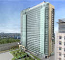
Design / Function: |
Phase I is the first phase of a multiphase development. The project will eventually result in the construction of approximately one million square feet of research space, one million square feet of ambulatory care and clinical office spaces, and one million square feet of parking and support services. Phase I is an 'L' shaped, four-level structure supported by steel frame with concrete shear walls, and three of four levels located below grade. Phase I is essentially three buildings which housed a three-level sub-grade research facility, a three-level sub-grade central utility plant (CUP), and a support services at stree level. The project is expected to receive LEED Silver Certification. |
|
Major Building Codes: |
International Building Code (2003) |
|
Zoning: |
C5 – Highest density Commercial | |
Historical Requirements: |
Not applicable to this project | |
Building Envelope: |
Phase I consisted mainly two types of exterior walls. Concrete masonry units (CMU) cavity wall system, consisted of 4" CMU veneer, 2" air space, 2" rigid insulation, self-adhere vapor barrier system, and 8" CMU backing. The CMU cavity wall system runs along the inner sides of the "L" shaped structure, adjacent to the future underground parking garage. Pour in place concrete foundation walls surrounded the exterior sides of the "L" shaped structure. Concrete foundation wall constructed with self-adhere vapor barrier on pour in place concrete wall with 2" foil faced semi-rigid insulation stick-pinned to exterior surface on the first 4'. |
|
Building Envelope: (Roof) |
Roof of the research facility consisted of EPDM membrane with tapered roof insulation system over concrete on steel deck. Future phases will be built above research portion of Phase I, and enclosed the roof of the research facility. Roof of CUP supports loading dock traffic with 4" concrete traffic topping over 2" rigid insulation on structural concrete slab. |
|
Primary Engineering Systems
Mechanical: |
The ventilation system for the research facility comprised of four 100,000 CFM air handling units (AHU) equipped with variable frequency drives (VFD). They deliver 100% outdoor air to three of the four fitted out levels the means of variable air volume (VAV) system. The four AHU are demand based, and supply airflow can be reduced to 50% of the design airflow. Two 120,000 CFM exhaust air handlers with heat recovery remove majority of the indoor air, and preheat the supply air. Other exhaust systems compensate for the remaining indoor air removal. CUP used two demand based 24,000CFM make up air unites (MAU) for ventilation. Air temperatures are controlled by air conditioning units (ACU) in individual equipment rooms. The chiller plant, one 2,000 ton steam turbine chiller and one 2,000 ton electric centrifugal chiller, produces 42°F chilled water. They reject heat by means of four 1,000 cooling towers with VFDs, and act as siphon in winter time for water side “free” cooling. These chillers provide chilled water to the AHUs, ACUs, as well as process chilled water (PCHW) loads. The boiler plant included four 800HP duel fuel boilers with VFDs and stack economizer. The boilers produce high pressure steam at 125psig for high efficiency distribution, and drive a steam turbine chiller at 120psig. High pressure steam is reduced to 70psig medium pressure steam for process equipments and domestic hot water heating. Steam pressure is further reduced to 2psig low pressure steam for humidification and building hot water loop re-heat. All sequence of controls for the building’s heating, ventilation, and air condition (HVAC) are performed by direct digital controls (DDC) system. DDC monitor all sensors, and adjust correspond controllers for the HVAC equipment based on design set points. DDC system is a part of the building management system (BMS) which enable authorized personnel to monitor, record, and operate the building for optimum performance. The building’s MEP infrastructure is expected to support City Hospital’s current activities as well as future programs. Additional mechanical and electrical equipments will be added to the CUP as part of future phases to increase capacity. |
|
Electrical: |
Electrical power is supplied by a Pennsylvania electric company on two 13.2KV service feeders via underground ductbank. The 15KV duel line switchgear with bus tie breaker, rated at 2,000A delivers electricity to three substations by means of secondary selective for improved reliability. Two 2,500KVA double ended substations with tie breaker, step 13.2KV to 480/277V, 3ф, 4 wires, and distribute services to the research facility and CUP respectively. A 5,000KVA substation steps 13.2KV to 4160V, 3ф, 4 wires for a 2,000 ton electric centrifugal chiller. Emergency/life safety demand is supported by two 2MW diesel powered generators. Additional switchgear and substation will be added to the CUP as part of future phases. |
|
Lighting: |
A variety of lighting fixtures are used in City Hospital Phase I. The illumination system consisted predominately of 32 watt T8 and UT8 lamps on 277V secondary distribution to lower power consumption. Compact florescent and incandescent lamps are used in special areas, such as a MRI room, for their ability to focus and dim respectively. Doubled height spaces, such as the boiler room, required high intensity discharge (HID) metal halide to illuminate floor. Light emitting diode (LED) technologies are also employed in emergency signage for minimal power consumption and longevity. Exterior illumination is not part of Phase I. |
|
Structural: |
The structural system for Phase I consisted of steel frame with concrete shear walls on shallow foundation system with spread footings. Foundation walls are integrated with structural frame via steel shear plates. Each 2’ thick shear wall has two curtains, vertical and horizontal reinforcement varies with height, and steel columns implanted for extra stiffness. The shear wall system, running from Level D to Level A, is sized to resist lateral forces transferred from future phases above. The composite floor system consisted of 4,000psi concrete on composite steel deck with shear studs. Steel beams ranged from W12 – W24 for the research facility, W8 – W30 for CUP, and bay width varies from 24’ to 33’. |
|
Construction: |
City Hospital holds a lump sum contract with Ballinger Architects to design the building, and a guaranteed maximum price contract with Turner Construction Company. The project construction is being coordinated by Turner acts as a construction manager at risk and holds lump sum contracts with its prime contractors. The construction on Phase I started in March 2005 and it is projected to complete by December 2007. |
|
Fire Protection: |
Phase I used an automatic sprinkler system for fire protection. Semi-heated spaces and loading area are protected with dry pipe sprinkler system for freeze prevention and electrical equipment rooms utilized an5k electrical actuated double interlock pre-action sprinkler system to prevent unnecessary water damage. All other areas have a wet pipe system with recessed flush type sprinkler heads for fire protection, and areas without ceiling uses upright sprinkler heads with protective cage guards. In case of a fire, the 250 HP electrically driven fire pump can deliver 1250 GPM of water to the sprinkler system for fire suppression. Fire extinguishers are also placed throughout the building for manual fire suppression. |
|
Transportation: |
Phase I is provisioned for twelve standard hydraulic elevators, and eight are installed as part of the phase. Eight elevator shafts are located near the core in the research facility for vertical transpiration Level A through D, and one of the elevator shafts is scheduled to link Phase I to all floors on future constructions above. CUP will have four elevators for personnel and equipment transportation. Phase I also has six stairwells located strategically throughout the building which are crucial to evacuation of occupants in case of an emergency. |
|
Telecommunication: |
All essential communication wirings, telephone system, security system, data system, and cable television system, are connected through a low voltage raceway support system. |
|
Special Systems: |
Information is not available. |