ROCKFORD, IL
PHILIP K. FREDERICK
Structural Option
| Home |
| Student Bio |
| Building Statistics |
| Thesis Abstract |
| Technical Assignments |
| Thesis Research |
| Thesis Proposal |
| Presentation |
| Final Report |
| Reflections |
| Senior Thesis e-Studio |
User Note: While great efforts have been taken to provide accurate and complete information on the pages of CPEP, please be aware that the information contained herewith is considered a work-in-progress for this thesis project. Modifications and changes related to the original building designs and construction methodologies for this senior thesis project are solely the interpretation of Philip Frederick. Changes and discrepancies in no way imply that the original design contained errors or was flawed. Differing assumptions, code references, requirements, and methodologies have been incorporated into this thesis project; therefore, investigation results may vary from the original design. |
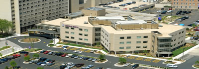
Swedish American Hospital
Heart and Vascular Center
- Building Statistics

*photo is a computer generated rendering superimposed on a picture of the site before construction
Building Name:
Swedish American Hospital Heart and Vascular Center
Building Occupant:
Swedish American Hospital
Location:
1400 Charles St
Rockford, IL, 61108
Function:
Hospital
Size:
Gross Area = 130,000 SF
Height:
4 stories (52'-6") plus a mechanical penthouse
above grade with a partial basement below grade
Project Team:
-
Architect
Perkins and Will Architects -
Engineers
Civil - ARC Design Resources, Inc.
Structural - Simpson Gumpertz and Heger Inc.
MEP - KJWW Engineering Consultants
Geotechnical - Testing Engineering Inc. -
Landscape
Thomas Graceffa and Associates -
Interior
Perkins and Will Architects -
Medical Equipment Planner
Turner Logistics Medical and Research Products Group -
Construction Management
Turner Construction Company in association with Schmeling Construction Company - Specifications
Kalin Associates
Dates of Construction:
Bid Package Issue Date : December 2004
Substantial Completion : February 2006
Costs:
Construction Costs = $35,000,000
Project Delivery Method:
*Requested Information and awaiting response
Architecture:
The Swedish American Hospital Heart and Vascular Center is the completion of Phase II in a three phase project design/renovation on the Swedish American Hospital Complex. The Heart and Vascular Center is a four-story medical building with a partial basement and mechanical equipment on the roof. Its design allows for future expansion by enclosing the roof (5th floor) into a mechanical floor and adding two future stories (6th and 7th floors). The building also serves as a bridge between two other adjacent buildings.
The primary building footprint is made up of 4 triangular wings surrounding a rectangular central core. Nurses stations are positioned at the center of each wing allowing nurses to monitor all patient rooms from a single location. A new lobby is located on the west end of the Heart and Vascular Center. The two story Lobby structure will serve as the new entrance into the hospital complex with a reception desk and waiting area.
Building Envelope:
Three different exterior wall systems are in place around the perimeter of the building. The most predominant is an architectural precast wall panel system made from lightweight concrete. Light gage metal framing is used as a backup system with an air gap, waterproofing, insulation and exterior sheathing installed between the framing and the precast veneer.
The second type of wall system utilizes 4" face brick with the light gage metal framing backup system to resist wind loads. Similar to the first type, it also includes an air gap, waterproofing, insulation and exterior sheathing between the framing and the face brick.
The final exterior wall assembly is a curtain wall system installed where there are large expanses of glass facade. These areas include the main entrance, located on the southern face of the Heart and Vascular Center, and around the court yard area, located on the north side of the entrance lobby.
Building Codes:
- IBC 2003 (with Rockford, IL, amendment)
- ACI 318-02 (Concrete)
- ACI 530-02 (Masonry)
- FEMA 350
- AISC 1999 (LRFD)
- AISC 341-02 (Seismic)
Zoning:
*Requested information and awaiting response
Historical Requirements:
*Not Applicable, not in historic district
Mechanical Systems:
The variable air volume (VAV) system used in the Swedish American Hospital Heart and Vascular Center is fed by 2 large roof top units, located behind a screen wall. Each unit is responsible for serving all floors on one half of the building, one serves the eastern half and the other the western half. For these units, 55° air is supplied to VAV boxes located in individual office and patient rooms. The VAV system uses hydronic reheat coils to warm the air to the desired temperature for each space.
For large spaces, such as the lobby and large glass curtain walls, hot water radiant heat baseboard units are installed to help control the space.
The exhaust system at Swedish American Hospital is unique to hospitals. It includes 2 central constant volume exhaust fans and 2 central variable volume exhaust fans. The two constant volume fans are for general use. The two variable volume fans are part of an isolation exhaust system with VAV controls at individual patient rooms. This allows any patient room to be closed off as an isolation room, if necessary, but all rooms will function “normally”, unless otherwise directed, to save energy costs.
Electrical Systems:
Swedish American Hospital is fed by a 13.8 kVa system with multiple transformers feeding the different buildings. Specific to the Heart and Vascular center, an additional transformer was added to help power the buildings as well as drawing load from other buildings.
The Primary distribution system, located in the basement, is composed of 480/277V panel boards supplying approximately 2500 amperes. The distribution is divided into 4 categories by code: Normal, Emergency, Critical, and Equipment. 480V are distributed from a branch system to a 208/120V transformer located in an electrical room on each floor of the Heart and Vascular Center.
Lighting Systems:
The lighting design in the Heart Hospital had one main goal in mind: have large open spaces with an abundance of natural light to help create a comfortable and stress free environment for patients. Lighting fixtures within the hospital use predominantly fluorescent and compact fluorescent luminaries. Outside the entrance lobby, metal halides illuminate the entrance canopy and other architectural features around the front facade.
Structural Systems:
The existing 4 story structure is framed together with steel frames with bolted flange plate moment connections. The structural system is designed to support an additional 3 stories (7 stories total) due to a proposed expansion. Lateral forces are balanced by the system of internal and external moment frames acting together.
The floor framing system is a steel beam and girder system acting compositely with a 3 ¼” thick concrete slab and metal deck. Composite action is achieved through the use of shear studs.
Interior columns bear on spread footings while exterior columns and supports rest on continuous footings running the perimeter of the building. Two slabs on grades are in place, one covering the basement floor and the second covering a portion of the first floor.
Construction:
The construction management for the Swedish American Hospital was done by Turner Construction Company, and in conjunction with Schmeling Construction Company. The project was completed in March 2006 for a Guaranteed Maximum Price (GMP) of $36,600,000. Construction on the project started in November 2004 with an initial bid of approximately $34M and a substantial completion date of February 2006.
The addition of the "Healing Garden" and other change orders temporarily delayed construction, but the structure was able to be fast tracked to help stay relatively on schedule. Bolted steel moment connections were able to be prefabricated and were quickly assembled in the field. A large Manitowoc 777 model crane capable of hoisting 181 tons was used for the steel erection.
Fire Protection:
Spray on fire protection is provided at all exposed steel structural elements. A 2 hour rating is provided for each floor assembly (beams and girders included), while a 1 hour rating is provided for the roof assembly. All vertical exits are surrounded by a 2 hour fire rating and all assemblies functioning as a "smoke barrier" are designed for a 1 hour minimum fire rating.
Fire stops and smoke seals are installed at all penetrations in fire rated assemblies (walls, floors, etc). Each fire protected penetration is labeled with the make and model of the fire stop and is initialed/dated by the installer. All penetrations are checked once a year to ensure that they are functioning properly.
Transportation:
Within the main plan of the Heart and Vascular Center there are 4 elevators (2 public, 2 private) located in the northwest corner of the structure. Adjacent to this elevator core is space for a 5th elevator for future expansion. A stairwell is also located next to the elevator core while a second stairwell is located on the opposite side of the building, at the southeast corner. These areas provide service to all floors of the Heart Hospital.
The floor plan for the 2nd, 3rd and 4th floors have 4 triangular wings extending from each side of a central rectangular core. These 4 wings serve as patient wings with nurses stations located at the center. Diagonal hallways are cut through the central core area allowing for quick travel from wing to wing in case of emergency. Nurses are able to monitor all patients quickly and from many vantage points.