ALEXANDER HOSKO
MECHANICAL OPTION
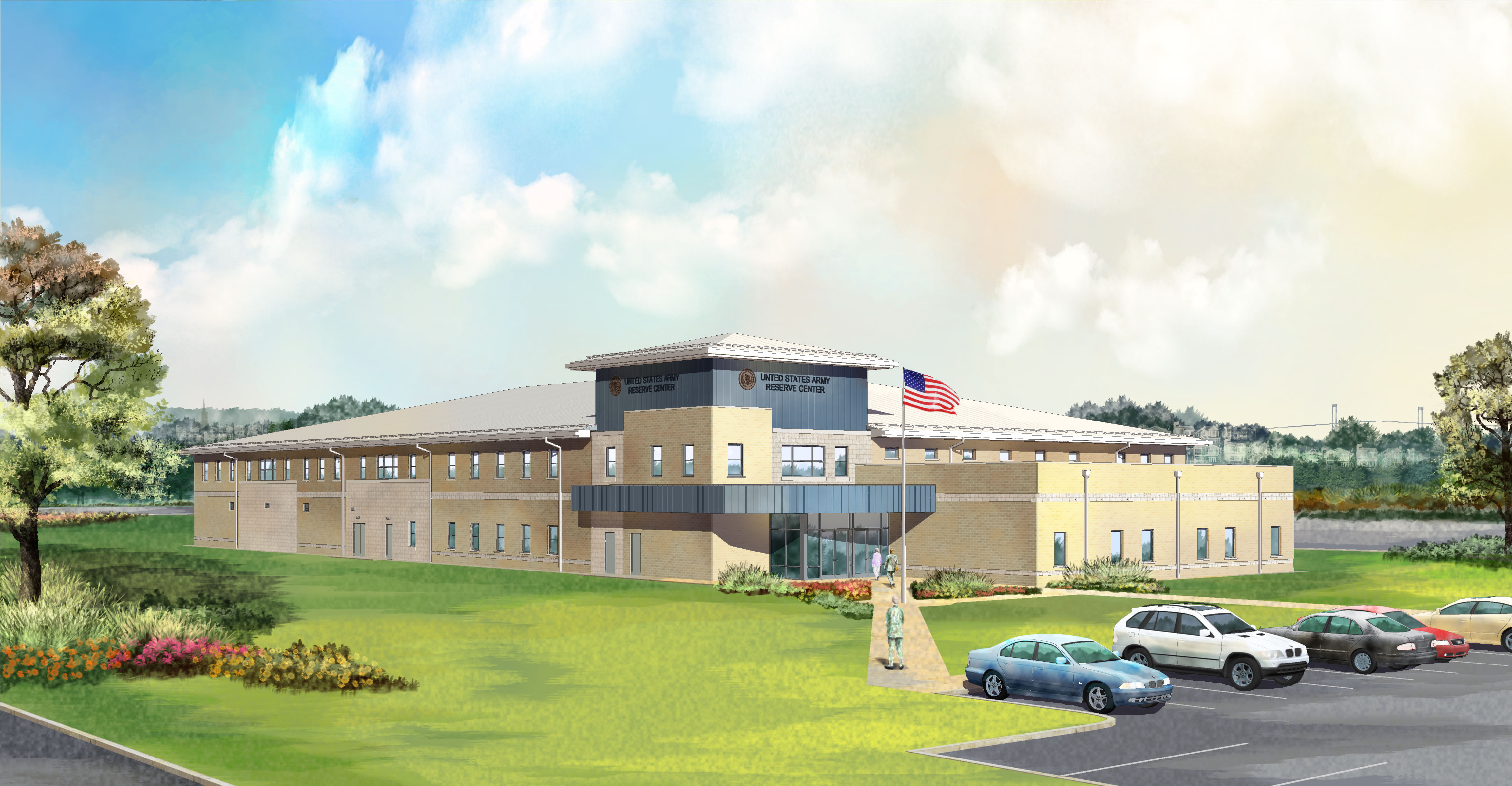
ARMY RESERVE CENTER
NEWPORT, RHODE ISLAND
| HOME | STUDENT BIOGRAPHY | BUILDING STATISTICS | THESIS ABSTRACT | TECHNICAL ASSIGNMENTS | THESIS RESEARCH | THESIS PROPOSAL | PRESENTATION | FINAL REPORT | REFLECTION | SENOR THESIS E-STUDIO |
|
ALEXANDER HOSKO MECHANICAL OPTION ARMY RESERVE CENTER NEWPORT, RHODE ISLAND |
|
|||||||||||
|
|||||||||||||
Building Statistics Part 1 General Building Data - Owner: U.S. Government - Department of Defense - Architect: Jason Bischoff – Baker and Associates - Mechanical Engineer: Douglas A. Barker – Baker and Associates To get to Baker’s website: www.mbakercorp.com Dates of Construction: The project was awarded on January 15, 2009. The estimated completion date is September of 2011.
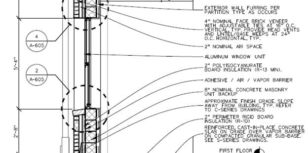
Zoning: The building is classified as Business Group B in the International Building Code as its primary occupancy. Its secondary occupancy consists of Assembly Group A-3 and Storage Group S-1 according to the International Building Code. Building Enclosure
Building Statistics Part 2
Construction The construction of the Army Reserve Center training building will be completed in the fall of 2011. An organizational maintenance shop and an unheated storage building will also be built. The general contractor for the job is J&J Contractors, Inc. A design-bid-build method was used for the project delivery method. Construction will include access for the disabled and will provide physical security measures such as maximum standoff distance from roads, parking areas, and vehicle unloading areas. Electrical 13.8 kV electricity shall be brought in from an existing manhole and then stepped down to 480/277V, three phase, four wires by a 750 KVA transformer. A 200 amp load break switch, current limiting fuse, and bayonet overload fuse shall be provided. Motors and other large electrical loads will operate at 480 volts and lighting will operate at 277 volts. Lighting Most of the Army Reserve Center will consist of fluorescent fixtures with electronic ballasts and energy efficient T8 lamps with an illumination level of 50 foot-candles. The storage spaces and mechanical/electrical rooms will have lighting levels of 20 and 30 foot-candles respectively. In order to save energy, occupancy sensors will be provided in accordance with ASHRAE 90.1. Mechanical The Army Reserve Center contains three air handling units. AHU-1 serves the first floor offices, is of the variable air volume type, and provides 3700 CFM of supply air which is 24% outside air. AHU-2 serves the second floor, is also of the variable air volume type, and provides 13,200 CFM of supply air which 18% outside air. AHU-3 serves the auditorium, is of the constant volume type, and provides 2100 CFM of supply air which is 64% outside air. The rest of the ventilation for several other spaces on the first floor is done using small unit ventilators. Each air handling unit is manufactured by Trane and contains a supply fan, return fan, cooling coil, heating coil, and filter. There are two boilers present in the Army Reserve Center. Both boilers have 959 MBH of heating capacity, are manufactured by AERCO, have enter water temperatures of 100 degrees Fahrenheit and leaving water temperatures of 130 degrees Fahrenheit.
There are two air-cooled rotary screw packaged water chillers piped in parallel in the Army Reserve Center. The chillers have capacities of 40 and 52 tons respectively, are both manufactured by Trane, and both have scroll compressors that use R-410A as the refrigerant.
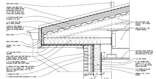
Structural The Army Reserve Center consists of two different types of structural systems. The first system is for the two story portion of the Army Reserve Center. It is made up of steel wide flange columns and beams that support a composite steel deck at the second floor and a pre-engineered light gage metal truss system at the roof. The second floor of the Army Reserve Center is composed of a steel beam floor framing which supports 2” galvanized composite steel deck and reinforced normal weight concrete, with an overall slab thickness of 4 ½ inches. In order to reduce vibrations, the floor beams are usually 8’0” apart. To support the roofing system, 1 ½” galvanized metal deck spans between framing members consisting of light gage pre-engineered trusses that are spaced 48” apart and span to steel girders framing into steel columns. The exterior walls, supported by the foundation system, are composed of 4” masonry veneer with 8” concrete masonry backup and 6” light gage metal stud backup at the first and second floors respectively. The second structural system of the Army Reserve Center is for the attached auditorium. It consists of steel joists that are supported by steel girders and columns. A 1 ½” galvanized metal deck spanning between steel joists is implemented to support the roofing system. The exterior walls, consisting of 4” masonry veneer with 8” concrete masonry backup, cantilever past the steel roof to form a low parapet around the roof’s perimeter. They are supported by the foundation system.
Fire Protection The Army Reserve Center shall be provided with an automatic wet pipe sprinkler system in accordance with NFPA 13 and UFC 3-600-01. The water for the sprinkler system shall be obtained from a different water line then the domestic water line. Each sprinkler system shall be provided with a OS&Y gate valve, backflow preventer, tamper switch, flow switch, test and drain valve assembly and drain line. Access shall be available to components of the sprinkler system that require access.
Transportation The Army Reserve Center has a vestibule at the main entrance located in the northeast corner of the building. Two other vestibules along the western wall also allow entry. There are two stairwells in the Army Reserve Center – one in the northeastern corner and another in the southeastern corner. There is one elevator in the northeastern part of the Army Reserve Center. Telecommunications Telecommunications in the Army Reserve Center will be from Verizon. Category 6 horizontal cabling shall be routed throughout the building in cable tray as open cabling. The assembly hall will contain a public address system. Cable television outlets are to be provided in break rooms, classrooms, the assembly hall and other spaces defined by UFC 4-171-05. An intercom/buzzer system will be provided at the entry vestibule with door release buttons provided in full-time offices adjacent to the entry.
|
User Note:Note: While great efforts have been taken to provide accurate and complete information on the pages of CPEP, please be aware that the information contained herewith is considered a work-in-progress for this thesis project. Modifications and changes related to the original building designs and construction methodologies for this senior thesis project are solely the interpretation of STUDENT. Changes and discrepancies in no way imply that the original design contained errors or was flawed. Differing assumptions, code references, requirements, and methodologies have been incorporated into this thesis project; therefore, investigation results may vary from the original design. |
Links to: Senior Thesis Main Page , Penn State AE , AE Computer Labs This page was last updated on April 26, 2011, by Alex Hosko and is hosted by the AE Department |