Welcome to Ian Gayman's AE Senior Thesis e-Portfolio
Building Statistics.
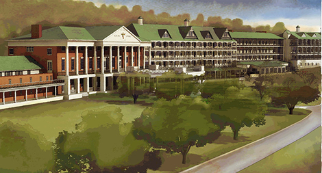
- Bedford Springs Hotel
- Location: Bedford, PA
- Operation Company: Benchmark Hospitality International
- Function: Hotel/Resort
- Building Size: Approx. 250000 sq. ft.
- Total Stories: ranges between 2 and 4 depending on building
- Project Team:
- Owner: Bedford Resort Partners, Ltd.
- CM: Reynolds Construction ( www.reynoldsconstruction.com )
- Architects: Corgan Associates, Inc. ( www.corgan.com )
- Structural Engineer: Hunt & Joiner, Inc. ( www.h-jinc.com )
- Start/Finish – December 05/May 07
- Overall Project Cost: $60 Million ( Cost includes buildings and surrounding grounds)
- Delivery Project Method: Design-Build
Architecture:
- Architecture design is historical for time periods of buildings construction; historical information is being obtained from CM. The hotel features a golf course, gardens, a spacious spa and health area, indoor and outdoor swimming pools, and a tavern area. The hotel was built around multiple natural springs making the hotel a function place for a resort area.
- National Code: IBC 2003
- Zoning: Commercial
- Historical requirements and classification on historical register being obtained from architect
- The multiple envelopes used throughout the buildings consist of mostly natural wood siding supported by stud walls; however brick and stone walls do appear due to the multiple periods of construction that took place over the ages. The roof system consists of a composition shingling reinforced by sheathing and truss systems, which repeats uniformly over the entire hotel.
Electrical/Lighting Systems
The electrical system from the utility company is routed through two 480Y/208V, 3-phase, 4W transformers. Type THHN/THWN feeders distribute power to sixty-six panel boards throughout the hotel. The different panel boards support a variety of loads, both 480Y/277V and 208Y/120V. The system is supported by a 625KVA/500KW, 480Y/208V, 3-phase, 4W emergency generator. HID outdoor lighting covers the gardens and close grounds areas. There is a combination of approximately sixty-eight different luminaries used on the project.
Mechanical System
The main mechanical room is placed in the Service Building on the elevated north side of the site. This area contains five hot water boilers (1840 MBH each), five cold water pumps for the HVAC system (1100-1200 GPM each), two 2-cell open-circuit cooling towers (2200 GPM each), and four domestic water heaters. Lines are run across a service bridge that connects the Service Building to the hotel. Mechanical rooms for self contained units that service public areas are located on the Pool Building mezzanine roof and the Colonial Building attic as well as ground floor rooms in the Colonial, Evitt, Stone, and Spa Buildings. The self contained VAV units located throughout the hotel supply between 8000 and 25500 CFM to there respective locations. Ventilation for guest room hallways is supplied from heat pumps in the Spa, Evitt, and Anderson Building attics; these heat pumps (SA CFM 1600-1800) emit 100% outdoor air. Each guest room contains a private water source heat pump which supplies 370 to 4000 CFM varying on the given room. The nineteen exhaust fans that service the hotel are located in the building attic areas. Fire suppression for exhaust duct work is sustained from a mineral wool sheetrock rap that encloses all necessary duct work.
Structural Systems
Structural Steel Frame
The structural steel framework for the project is a basic structure type. Columns for the steel erection are square tube steel and elevator shafts are tube steel as well with cross bracing for support. Steelwork was typically erected once footers were poured and in place. The steel was erected with a mobile crane, terrain lift, or mobile jack depending on size, height, and location.Cast in Place Concrete
Cast in place concrete was used all over the site; its primary use on the project was for footers, floors, retaining walls. Any formwork that was required for a pour on the site was set up in a vertical system. Typical placement methods used over the site were buggies or a pump truck.Masonry
The masonry walls on this project were both bearing and veneer. Since this was a historical renovation, the brickwork was repointed and relayed to restore the exterior façade. Brickwork was also reconstructed and replaced in exceptionally deteriorated areas. Due to the structure being three stories high, scaffolding and man-lifts were used for the work. For the building with veneer masonry walls, brickwork was only relayed in the needed areas.
Other Construction Systems
Demolition Required
The demolition that was called for on this project was extensive; the buildings had sat unattended for approximately 18 years and were in disrepair. The demolition removed the majority of the interior walls minus established hallways as well as the interior side of the building envelop. Selected parts from the buildings were salvaged such as all components of the doors, windows, and molding. Other demolition that occurred was the removal of asbestos, MEP components, and damaged floors from the high water table. Building demolition did occur across the site; several of the outer buildings were demolished and 3 of the 5 stories were removed from the Service Building. After construction had begun, crews returned to remove lead paint from the exterior of all of the buildings.Support of Excavation
The excavation support systems used on this project were beam and lagging supports for the soils that were removed from the hillside during foundation and retaining wall installation. Dewatering systems were used in areas that directly affected the foundational systems. These temporary systems consisted of sump pumps moving water by hose to storm water drainage piping. The permanent dewatering systems that will be used in the hotel will be located in sump pits at all established elevators. These pit pumps will keep the water level at tolerable point so that interior aspects of the hotel will not be damaged by flooding.