| Building
Statistics
|
|
|
| Interdisciplinary Science &
Engineering Building |


|
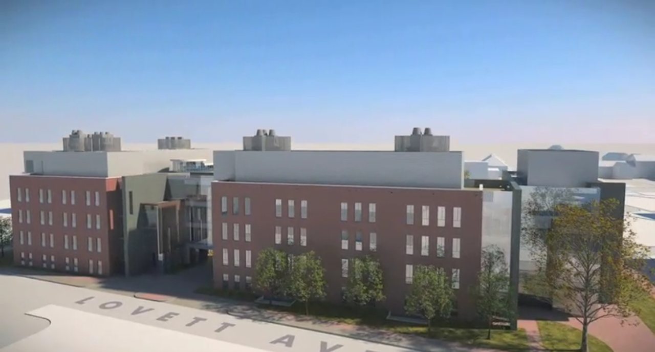
Building Name: Interdisciplinary Science and Engineering Building Location: University of Delaware/Newark, DE 19716 Site: On the corner of Lovett Ave. and Academy Street. Occupancy Type: Classroom/Office/Lab Size: 194,000 SF Floors: 5 floors above grade (4 occupiable, 1 mechanical penthouse) 1 floor below grade (Mechanical rooms) Project Team: Owner: University
of
Delaware Architect: Ayers
Saint
Gross
Architects
and
Planners MEP: Mueller
and
Associates Structural: Thornton
Tomasett Civil Engineer: Rummel
Klepper
&
Khal Lab Consultant: Research
Facilities
Design Biohabitats, Inc www.biohabitats.com Dates Start: Spring 2011 Date Finish: Fall 2013 Project Budget: $140M Construction Budget: $105M Project
Delivery
Method:
Design-Bid-Build Enthalpy Wheel  Photocell-Based Sensor  Steel Pedestrian Bridge shown below  Structural Skeleton (Looking SW)  |
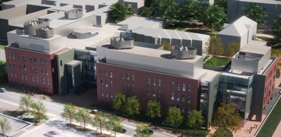
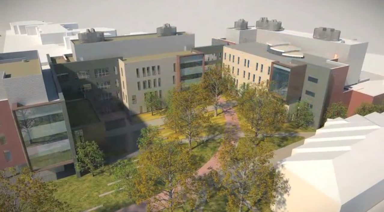
Architecture: The University of Delaware’s goal on this project was to create a building that would allow the research that was going on in their labs to be directly connected to the curriculum taught in their classrooms so that the students may learn through real life problems. ISEB will bring together physics, biology, and chemistry and push their students to solve today’s energy based problems. This required a unique building, one that would sustain both the classroom and lab environments.
To
delineate
the
two
uses,
the
architect
divided
the
building
into
two
wings:
An
east
(research)
wing
and
a
west
(teaching)
wing.
These
wings
are
joined together by a
bridged
walkway to maintain that bond between the classroom and research. The
architect
has meshed together brick, stone and glass to give an organic feel to a
cutting
edge building. The buildings day lighting, solar panels, and some
rooftop
vegetation give a hint to a passer by or an occupant that this building
is one
in which today’s energy issues will be at the forefront. Facade: The
architect has incorporated many different materials and wall systems to
give
the building an organic feel and demonstrate its many uses. At the core
of the
building are the classrooms and laboratories which can be identified by
the red
brick veneer. The interior spaces such as the offices, cafeteria, group
study
areas, and open offices have a more open feel and can be identified by
the many
different types of glass, stone, and metal wall assemblies. In total,
the wall
facades for this building include brick veneer, aluminum curtain wall,
stone
rain screen, insulated metal panel wall, and a non operable aluminum
window
system. Rooftop: ISEB has many setbacks in its floors which creates multiple rooftops. The lowest of which is the roof over the cafeteria/dining area which the architect has chosen to cover with vegetation. The vegetation roof consists of the fallowing materials from bottom to top: concrete slab, rigid insulation, moisture retention mat, drainage board with aggregate, growing medium. Another predominant feature of the ISEB roof is a monitor roof which provides daylight to all of the floors below except the first floor. This monitor roof is the base for a collection of photovoltaic panels. Most of the other roofing is a fully adhered roof membrane over tapered insulation. The unsightly rooftop mechanical equipment is surrounded by a metal mesh roof equipment screen. Sustainability: Not only does ISEB have the usual pressure of incorporating sustainability into its design that most buildings being build today face but the goal of this building is to create an environment in which topics researched in the labs may be carried over into the classroom, one of which is renewable energy. This building starts on the outside with its green roof and photovoltaic solar panels which help to meet the stringent demands of a lab facility. Day lighting is abundant throughout the building through its many window panel systems and the monitor roof. There are also metal mesh screens that allow daylight in but cut down on direct sunlight. The sustainability theme is then carried inside to the guts of the building. The labs require 100% outside air so these AHU’s incorporate forms of energy recovery, either enthalpy wheels or heat pipes, depending on the space requirements. Variable frequency drive pumps are used in the hydronic systems and fluid coolers on the roof take advantage of cool winter temps when there are winter cooling loads in the building.
The building receives steam and chilled water from the Campus Utilities Plant (CUP). The steam is converted to hot water in a steam-to-water heat exchanger, which provides the buildings heating requirements. Chilled water, from the University of Delaware’s campus chilled water plant, is fed to a water-to-water flat plate heat exchanger that meets the buildings chilled water needs. An electric drive stand-by chiller is on site, in the basement mechanical room, and consists of 6 modules each sized at 50 tons (two of which incorporate hot gas bypass).Two fluid coolers with a nominal cooling capacity of 240 tons are on site to provide to reject heat from the standby chiller if the heating/reheat loops do not need it. There are 10 total AHU’s serving the building that are located in the fifth floor mechanical penthouses. Each of these seven AHU’s fall into one of two system types, either recirculating or 100 percent outdoor air. Air handling units 1, 2, & 10 are of the recirculating air system type. They serve the builds classrooms, offices, common spaces, and corridors. Pressure independent, Variable Air Volume (VAV) terminal units will be provided for each temperature control zone of the system. The other seven AHU’s (3, 4, 5, 6, 7, 8, & 9) are the 100% outdoor air units that serve the builds cleanroom, research, and instructional labs. These seven 100% outdoor air units all contain some form of energy recovery. Enthalpy wheels are used for spaces in which contamination of the supply air from the exhaust air is not critical and heat pipes for the units in which supply air contamination can not be risked (with the exception of AHU 9 which handles the clean room make-up air and has no energy recovery). Electrical Medium voltage (34.5 kV) power is supplied from the East Campus Utilities Plant. This power is supplied via two primary service entrance feeders which serve a dual primary-secondary indoor double-ended unit substation. Selection of either 35kV service feeder is switched by medium voltage fused switches on either end of the substation. The substation transformers are rated at 1500/1995 kVA. Power is then distributed throughout the building at 480/277 volts. Step-down transformers and panels are located throughout the building in dedicated electrical rooms on each floor.
The
majority
of
the
lighting
will
be
provided
by
energy
efficient
fluorescent
lamps.
Spaces
with
high
ceilings,
like
lobbies
and commons areas, will utilize ceramic metal halide and LED
lamps.
Tungsten-halogen sources are used where accent lighting is required.
Daylight
harvesting will be provided for spaces with abundant natural light.
This is an
energy savings measure and will include photocell-based control of the
spaces
lighting fixtures. The labs and clean room require elimination of Ultra
Violet
light contributions from the lighting fixture therefore the lighting
fixtures
in these spaces will implement filtered lenses or lamp sleeves.
The lateral system
for ISEB is a reinforced concrete shear wall design, consisting of a
total of 11 shear walls. The gravity system
is a
mixed type, consisting of two-way slabs with edge beams, flat plate,
one-way
slabs and joists. The majority of the slabs are 12" two-way slabs with
either 12" or 8" drop panels. Beam size range from 48x52 to 18x32.
Concrete columns from the basement to the fourth floor are primarily
24"x24" with some 36"x18" opposite the shear walls. The fifth floor
penthouse is supported by w12x40 steel beams. The foundation system
consists of mirco-piles, with
the
basement slab elevation at approximately two feet below the water
table. Strict
vibration control is needed for imaging suites and laboratories
(33-2,000 micro
inches per second). Another distinguishing feature of this building is
the pedestrian
bridge joining the research and classroom wings which is a structural
steel
design. This steel design consists of W21 girders, L6x6 & W2+Bent
Plates spanning the girders, and a 6 1/2" composite deck and slab. The
Monitor roof is framed with W12x26's and HSS8x4's.
Telecommunications
service are extended to the building from the existing Transportation There are a total of four stairways going from the 1st to 4th floors of the building. These stairs are located on the ends of each building wing. Three elevators move occupants from the 1st to 4th floors. There is one for each end of the building and one in the middle of the building near the bridge.
|
Note: While great efforts have been taken to provide accurate and complete information on the pages of CPEP, please
be aware that the information contained herewith is considered a work‐inprogress for this thesis project. Modifications
and changes related to the original building designs and construction methodologies for this senior thesis project are
solely the interpretation of Johnathan Peno. Changes and discrepancies in no way imply that the original design
contained errors or was flawed. Differing assumptions, code references,requirements, and methodologies have been
incorporated into this thesis project; therefore, investigation results may vary from the original design.


