Welcome to Jayme's AE Senior Thesis e-Portfolio
Building Statistics Assignment
Part I: General Building Data | Architecture
Part II: Mechanical | Electrical | Lighting | Plumbing | Structural | Fire Protection | Transportation | Telecommunications | Security | LightningProtection | Construction
Part I
Building Name:
Location and Site:
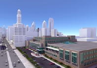
The property is located on North Broad and 15th streets between Callowhill
and Buttonwood streets, 6 blocks north of City Hall. It is adjacent to the
historic
This centralized location will be more accessible since it is served by public transportation and will be more efficient since all administration services will be at one location.
Building Occupant Name:
Occupancy and Function Type:
The building was originally built as a printing press used by different
newspapers in
Size:
Gross Measured Area - 848,000 Square Feet
Building Footprint Area - 161,000 Square Feet
Number of Stories Above Grade/Total Levels:
6 stories above grade including ground floor and floors 1 through 5
8 total levels including those above grade, a basement and mezzanine
Primary Project Team:
Owner: Archon Group, L.P.,
General Contractor/CM: Turner
Construction Company,
Architect: Hooper Shiles Architects,
MEP Engineers: Cannon
Design,
Site/Civil Engineers: Gladnick
Wright Salameda,
Structural Engineers: Thorton
Tomasetti Group,
Dates of Construction (Start – Finish): December 2003 – May 2005
Cost Information: $90 Million
Project Delivery Method: Guaranteed Maximum Price
Architecture Design And Functional Components:
The original building was built as a printing facility in 1948. Two major additions were constructed during its operation, in the 1960s on the north side and in the 1980s on the south side.
In 2000, Philadelphia Newspapers Inc. sold the building to Archon Group L.P.. Current core and shell renovations have been designed to accommodate approximately 470,000 square feet of rentable area including office and common area, conditioned storage and office expansion area.
Interior construction included new core toilet rooms, new elevator shafts
and modifications to existing shafts. New lobbies were provided at
Exterior wall refurbishment included new insulated glass windows, lobby entrances, insulated glass curtain wall systems and re-glazing with insulated glass selected existing windows and curtain wall systems.
An new architectural highlight is a new three story atrium with skylights which provides visual connectivity between the 1st, 2nd, and 3rd floors.
Major National Model Codes
BOCA 1995
NFPA
Zoning: Business Occupancy
Building Envelope
The exterior of the building is of brick masonry, limestone and architectural pre-cast concrete with limited curtain-wall and window areas.
The exterior wall of the original building is primarily of brick masonry with CMU back-up. The north addition is architectural pre-cast concrete and the south addition is limestone with CMU back-up. The exterior walls are typically capped with a limestone coping at the parapet. In designated office areas on floors 1 through 5 new insulated gypsum wall board was added. Some existing winders we re-glazed with new insulated glass.
Building entrances were equipped with card key access and commercial-grade code-compliant hardware. Secondary entrances and fire stair exits were provided with galvanized steel hollow metal doors and frames with commercial-grade code compliant hardware.
The roof consists of an insulated 3-ply modified bitumen roofing system. Modifications include accommodating base building improvements and new penetrations including the skylight over the atrium, new roof dunnage, and base building mechanical, plumbing, and electrical penetrations.
Existing Units
The existing two 15-ton and one 10-ton packaged rooftop HVAC units that
served the original 3 elevator lobby areas on each floor were kept for core
space.
Heating
For heating, the AC units on each floor are provided with an electrical
heating coil. Electrical cabinet heaters, unit heaters, and strip heaters
service stairways, entrances, utility areas and toilets. Miscellaneous heating
is provided with electrical unit heaters.
Outdoor Air Ventilation
Outdoor air ventilation is provided by a pressurized air duct from a mounted
outdoor fan with a motorized damper control at the mechanical rooms on each
floor.
Condenser Water
Condenser water is distributed by two pumps piped in parallel (one standby,
each rates at 4,500 gpm). The condenser water feed is treated with automatic
chemical feed unit and side stream filtration system
AC Units On Each Floor:
First Floor North Portion — Two 80-Ton AC Units
First Floor South Portion — Two 80-Ton AC Units
First Floor Infill Building — One 80-Ton AC Unit
Second Floor North Portion — Two 90-Ton AC Units
Second Floor South Portion — Two 90-Ton AC Units
Third Floor North Portion — Two 100-Ton AC Units
Third Floor South Portion — Two 100-Ton AC Units
Third Floor Infill Building — One 90-Ton AC Unit
Fourth Floor — One 100-Ton AC Unit
Fifth Floor — Two 80-Ton AC Units
Automatic Temperature Control
The automatic temperature control (ATC) system for the base building mechanical
equipment is comprised of
— Time clocks for the toilet exhaust system and the electrical closet
exhaust system
— Thermostats for all the elevator machine room exhaust fans
— Smoke detectors interlocked with all DX AC units on each floor
— The DX units on each floor are tied into one sub-control panel in
each MER. The integrated ATC/MNS system interfaces with all DX AC units’
sub-control panels cooling tower, condenser water pumps, return air fans,
OA fan, toilet exhaust fans and slit AC units.
— The atrium purge fans are interlocked with the fire alarm system.
Exhaust Systems
Toilet Exhaust — New toilet exhaust is provided for the new core
toilet areas, three “mushroom” type exhaust fans connected to
ducts routed within the toilet room.
Electrical Closets — New plenum exhaust is provided to each new electrical
closet on each floor. Slit AC units serve the transformers on the basement
level.
Elevator Machine Rooms — New exhaust fans with thermostat are provided
in each new elevator machine room. Supplemental AC units (3-ton each) serve
the new elevator machine rooms.
Basement Level, Mezzanine, and Ground Level Storage Space — Exhaust
required is based on the Philadelphia Building Code (0.05 cfm/sf).
Atrium — Smoke Purge: See Fire Protection.
Electric Service
The electrical service is a high tension 13,200 volt service. Three separate services are in the building, each consists of three double-end medium voltage switchgear sectionals located in the main electric room. Each double end switchgear section has two 15 KV cable connections or services to separate buses in the switchgear and an automatic tie-circuit breaker between the two buses. Each 15 KV service can provide power to the total load connected to the double-end switchgear. This type of arrangement is a primary select system, the downstream distribution equipment can be powered by two separate sources. This increases reliability because of the two power sources. Only one service in the building is active—Main Service 1B, with Main Service 2B and 3B inactive.
The electrical service enters the building through a 12-way underground ductbank and terminates in a PECO cable vault at the mezzanine level. There are six cables connected to the existing distribution equipment and six designed for future use. The existing cables connected to Main Service 1B didn’t have the capacity to accommodate the new loads for renovations. To increase the capacity of the existing service, a parallel set of 15 KV cables (same size, type, length) were installed to the double-end switchgear. Main Service 1B increased to 10MVA with primary select configuration.
Building Power
Existing Substation
An original 1500 KVA secondary unit substation is connected to the Main
Service 1B, which steps down the voltage from 13,200 volts to 480/277 volt.
This substation serves base building core loads: lighting, general receptacles,
and emergency distribution panel. The existing emergency service is connected
to a 150 KW diesel generator. The emergency loads are fire alarm, life safety,
and passenger elevators PE-1 and PE-2. Existing conduit riser from the 1500
KVA substation in Room G14 was relocated because it passed through a new
elevator shaft. The original distribution connection to the 1500 KVA substation
was modified to accommodate new loads in the basement level, mezzanine level,
ground floor, and core building.
New Substation
Power for the 1st through 5th floors office space is distributed from new
substations, one substation providing power to the east electric closets
and the other to the west electric closets. The two new 3000 KVA 480/277
volt secondary unit substations are connected to a 4000 amp bus duct riser.
A 480/277 volt distribution panel and feeder is provided to each mechanical
room. The mechanical panel provides power for HVAC equipment on the floor.
In each electric closet a 480/277 volt power panel is provided. Connected
to the power panel is a tenant lighting panel and a transformer for 208/120
volt receptacle power.
Improvements on the 1st through 3rd floors include 500 amp, 208/120 volt
main receptacle panel and on the 4th and 5th floors 400 amp, 208/120 volt
two-section receptacle.
Lighting panels are fed from the base building substations at 480/277 volt. Lighting panels for tenant improvements are located such that the maximum branch circuit length will be less than 150 feet.
General lighting is provided for base building areas including MEP rooms, toilet rooms, vaults, loading docks, lobbies, entrances, and stair towers.
Domestic Water System
The original plumbing system water demands are supplied by an 8-inch water
service which originates from 15th Street and enters the building at the
Mezzanine Level.
The original reduced pressure zone backflow preventer is relocated at the Mezzanine Level to facilitate relief discharge to 15th Street. A new domestic water booster pump is provided to the original water service next to the original booster pumps in the basement level mechanical room.
The original discharge main from the pumps is installed in the Basement Level ceiling which supplies two original separate 3-inch risers serving new Base Building core toilet rooms at the north and south ends of the building. Renovations include a new 4-inch cold water riser to serve the new east end toilets, each riser provided with a 1-1/2-inch valved outlet at each floor for PSD use.
Hot Water System
Hot water for the Base Building core toilet rooms is generated by electric
water heaters located above the ceiling of each core toilet room.
Sanitary Waste and Vent System
Above grade sanitary waste is drained by gravity to existing building sanitary
sewers and the vent stack terminates above the roof. Building sanitary sewers
are connected on 15th Street.
Sanitary drainage below street level is connected to ejector pits provided
with duplex ejector pumps. The ejector pumps are connected to the emergency
power system. Toilet rooms, mechanical rooms, and the cooling tower at the
5th floor are provided with floor drains and general floor drains are provided
with trap primers.
Storm Water System
Roof areas are provided with drains connected to leaders and horizontal
storm piping to building storm sewers at 15t h Street. All horizontal storm
piping is insulated to prevent condensation.
Natural Gas
The original 3-inch gas service from Buttonwood Street is capped at the
building control valve.
Plumbing Fixtures
New plumbing fixtures are handicap accessible as required by code, wall-mounted
elongated, commercial-grade vitrified china with water conserving flush
valve operators.
Lavatories are drop-ins with metered hot- and cold-water faucets.
Electric water coolers are stainless steel and handicap accessible.
Designed for ordinary hazard (Group II) occupancy and complies with the latest Philadelphia Building Coad, Fire Department, and NFPA 13.
Water Service
An 8-inch existing water service enters the building at the Mezzanine Level
at 15t h Street and then drops to the Basement Level pump room where it
supplies an existing 1250 gpm diesel engine fire pump and electric jockey
pump. This 8-inch main from the fire pump runs in the ceiling of the basement
level and supplies 3– to 6-inch combination riser/standpipes at the
three 15t h Street stair towers and 3– to 6-inch combination riser/standpipes
in each of the three Broad Street stair towers.
The combination riser/standpipes are sized to protect a 50,000 square foot zone and are provided with a 4-inch control valve assembly and a 2-1/2-inch fire hose valve at each floor landing. New fire protection piping is tapped to the six existing fire protection risers.
Control System
Valves controlling the fire protection system are provided with tamper switches
and water flow indicators connected to the fire alarm system.
Sprinkler System
The Base Building includes a wet sprinkler system for the Basement and Ground
Floor Levels and there is also an existing pre-action sprinkler system located
in the basement level. The sprinkler system in the load dock areas remained.
Sprinkler protection is in all Base Building areas including mechanical
rooms, storage areas, core toilet rooms, utility shafts, and elevator shafts.
Smoke Purge
A smoke purge system is required in the 3 story atrium. The three 20,000
cfm roof mounted exhaust fans with motorized dampers are capable of six
air changes per hour.
Fire Alarm System
The fire alarm system is a modular addressable system which is expendable
and consists of a central fire command center. The fire alarm systems consists
of manual pull stations, elevator recall, sprinkler water flow detection,
tenant terminal cabinets, HVAC equipment smoke detection and horn and/or
strobe notification.
The original structure is in the center of the facility and is a reinforced concrete structure of primarily flat plate floor construction with some beam and slab areas.
The first addition to the north end of the main building occurred in the 1960s and is a structural steel frame with concrete slabs on metal deck. The second addition to the south end of the main building occurred in the 1980s and is a structural steel frame with concrete slabs on metal deck. Other modifications in 2001 include additions to the 2nd and 3rd floors using steel and concrete construction.
Over time floor areas were infilled and reinforced to accommodate printing equipment. This included topping slabs to partial floor infills.
Base Building improvements included modifications to accommodate the new lobby schemes, atrium, shafts, stairs, and elevators.
Areas designated for office use have a minimum live load capacity of 125 psf, except a part of the 4th Floor where it is designated to accommodate 100 psf live load.
Column extensions and steel roof dunnage were provided to support the new cooling tower. All loads were transferred through the existing column extension.
The following elevators provide vertical transport within the building:
One existing 20,000 pound traction-type freight elevator located at the
north loading dock serving the Basement to the 3rd Floor.
Cab size: 11’4”W x 14’0”L x 9’0”H
One existing 10,000 pound traction-type combination passenger/freight elevator
located at the southwest core adjacent to the central loading dock and the
15th Street service entrance serving the Basement to the 4th Floor.
Cab size: 7’8”W x 9’2”L x 9’0”H
One 10,000 pound freight lift located at the southwest core serving the
4th Floor to 5th Floor. This lift is situated in a separate shaft positioned
adjacent to the existing 10,000 pound passenger/freight elevator (above)
and allows service from south loading dock to 5th Floor.
Cab size: 7’8”W x 9’2”L x 9’0”H
Two existing 3,500 pound traction-type passenger elevators located at the
east core serving the Basement to the 5th Floor and the Broad Street main
entrance lobby.
Cab size: 6’3”W x 8’8”L
Two new 3,500 pound traction type passenger elevators located at the east
core serving the Basement to the 5t h Floor and the Broad Street main entrance
lobby.
Cab size: 6’3”W x 8’8”L
Two new 3,500 pound traction-type passenger elevators located at the west
core serving the basement to the 5th Floor and the 15th Street main entrance
lobby.
Cab size: 6’3”W x 8’8”L
Information regarding telecommunications has been requested.
The entire building is secured and protected by a closed circuit television (CCT) and key card access.
Access to the building is by card keys and all entrances are monitored
by a CCT system reporting to a manned central security station at the
Provided at the medium voltage double-end switchgear as required by PECO. A lightning protection grid is provided on the roof.
Information of construction details has been requested.