
Welcome to Nicole's AE Senior Thesis e-Portfolio
Building Statistics
General
Building Data:
• Building Name: Wellington at Hershey’s Mill
• Location and Site: 1361 E Boot Road West Chester,
Pennsylvania 19380
• Building Occupant Name: Wellington Retirement
• Occupancy or Function Types: Assisted Living Community
• Size (Total Sq. Ft.): 370,000 Sq. Ft.
• Total Number of Stories: 5 Stories
• Number of Stories Above Grade: 3-4 Stories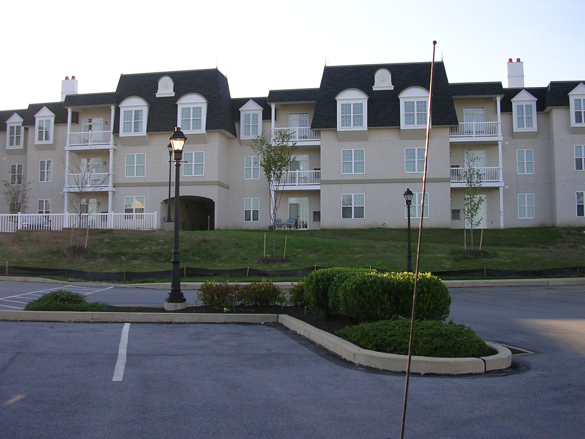
• Primary Project Team:
o Owner: MSL Associates Ltd.
o Architect: MSL Associates Ltd.
o MEP Engineers: Sebastian & Sons, Inc.
Website: www.jfsebastian.com/
o General Contractor: Caldwell, Heckles & Egan Inc.
(CH&E)
Website: www.cheinc.com/index.htm
o Electrical Contractor: State Electric
Website: www.state-mcf.com/
o Structural Engineers: P.W. Moss & Associates
•
Dates of Construction (Start-Finish):
o Planned: December 1, 2003 – August 1, 2005
o Actual: December 1, 2003 – August 15, 2005
• Cost:
o Overall Project: $20,700,000
o Soft Costs: $5,300,000
• Project Delivery Method: Design-Bid-Build
Building System Information:
Architecture: Wellington at Hershey’s Mill was designed
with the future inhabitants in mind. Luxury is a main theme in the design
but functionality is under the surface, providing a beautiful place for
retirees to live.
The partial lower level of Wellington contains the medical suite that houses
two doctors’ offices, exams rooms, and nurses’ stations. For
entertainment, a lounge, auditorium, beauty salon, pool and courtyard were
included. The kitchen, laundry room, and exercise and fitness center round
out this level.
The lobby/garage level includes a bistro, the dining room, another lounge,
a country store, and a bank. For more leisure, a library, billiards room,
meditation room, computer room, card room, and hobby room are all in one
place. There are also offices in the building for the Wellington employees
which provide close proximity for the tenants. This level also showcases
a veranda and many balconies.
The first through third floors are similar with a few variances on the first
floor plan. The same types of apartments are in the same location for each
floor.
Building Envelope: The exterior of Wellington
exudes the feeling of luxury the Architects intended. A porte cochere is
constructed of 2x4 stud framing with a conventional stucco finish. The roof
is framed with scissor trusses and finished with fiberglass shingles and
PVC spires. The main entrance contains a vestibule with double doors.
The exterior walls are different for the lower and upper halves of the building.
The lower level and lobby/garage level exterior walls are cmu block with
a red stucco finish for the parts of the wall above grade. The first through
third floors’ exterior walls are wood stud framing with two layers
of white stucco finish.
For the lobby level, there are balconies and a veranda that feature beautiful
1’-4” long by 1’-0” wide columns that are made up
with 2x4’s and 1/2” OSB and then finished with two coats of
white stucco. Within the façade is the 6x6 post column that is the
actual support. The balconies for each exterior apartment use 10”x10”
fiberglass columns that are thinner versions of the lower level columns.
For every balcony, a 36” high PVC railing was installed.
Construction: Construction began on Wellington
in December of 2003 and consisted of three phases. The first phase was to
be finished within 8 months of the start date and the second and third phases
were scheduled for 20 months after the start date. Due to miscommunications
mainly between the architect and the CM, the first phase was not finished
in the allotted time. After coming to an agreement, the contractors worked
well together and completed the next two phases by August 15, 2005, just
two weeks later than the goal of August 1, 2005.
The CM’s contract with the owner was a bid guaranteed max price contract
and the original cost was set at $19,400,000. Setbacks and change orders
caused the final price increase to $20,700,000.
Zoning and Historical: The zoning for
Wellington consisted of two parts. R1 Planned Residential Development for
the first phase of Wellington and R2 for the second phase. There is protected
vegetation on a section of the Serpentine Stone Ridge that runs behind Wellington.
Major National Codes: Wellington was designed under the Boca 1996 Building
Code and construction permitted under the International 2000 Building Code.
Electrical: The main electrical service
to the building is 35KV, which feeds a 1000 KVA transformer. The secondary
voltage goes to a main 3000A switchboard, 480/277V, 65 KAIC. This switchboard
feeds all four elevators, HVAC equipment, generator and three electric rooms.
Each electric room has one 500 KVA transformer 480 TV 120/208 and a 2000A
switchboard that feeds an 800A panel on each of the 3 floors. There is also
a 300 KW generator for emergency power at 480V, one emergency panel for
480/277V lighting and a 75KW transformer 480 TV 120/208 panel for lighting.
One elevator is on emergency power, each apartment has their own 125A service
and panel. The generator also supplies power to a 40 HP fire pump.
Lighting: All of the common areas consist
of incandescent 120V lighting while the office, game room, doctor’s
office, and parking garage are fluorescent 277V. Each apartment includes
lighting fixtures and paddle fans.
The site lighting consists of metal halide 277 V lighting on a 12 foot pole
with carriage type fixtures.
Mechanical: The mechanical contractor
divided the project into two areas: the common area and the residential
area. The common area consisted of the main lobby, administrative offices,
dining room, recreation wing, auditorium, and medical offices. The 197 apartments
along with their corridors and stairwells made up the residential area.
All of the areas within the common space excluding the dining room have
split system heat pumps while the dining room and kitchen are serviced by
packaged rooftop heat pumps. For the indoor pool, a split system dehumidification
system was used.
The residential HVAC systems included packaged thru-wall heat pumps for
each apartment and packaged rooftop heat pumps for the main corridors.
All rooftop air conditioners supplied fresh air or fresh air was ducted
to the split system air handling units. Exhaust fans were installed in all
bathrooms, the parking garage, pool, and beauty salon. For heating in stairwells
and by exterior exits, electric wall and ceiling heaters were set up. The
parking garage was heated with heaters in the ceiling plenum.
Stand alone thermostats control all the HVAC systems in the building. The
apartment thermostats are manual while the corridor thermostats are seven
day programmable.
Structural: The structural design of Wellington
is made up partially of masonry, concrete and steel in the lower levels
and the foundation and wood framing for the first through third floor. The
masonry walls are union-self-supporting elements and are dependent upon
diaphragm action of the metal deck for stability and for resistance to wind
and seismic forces. The steel structure is a union-self-supporting steel
frame and is dependent upon diaphragm action of the metal roof deck also
for stability and resistance to lateral forces. The codes followed in the
design were ACI530-95 and ASCE5-95.
The foundation of Wellington is 4” concrete slab-on-grade with 6x6-W2.0xW2.0
WWF over 2-4” porous fill. The continuous footing is 2 feet in width
and the column footings range from 3’x3’ to 4’-6”x4’-6”.
There are two pier sizes in the foundation; 18”x18” and 20”x20”.
Column sizes are HSS6’s, HSS8’s, and W10’s. The foundation
wall is primarily 12” cmu block with a section of it being 8”
cmu block.
The lobby floor framing has a 4” concrete slab over 1-1/2” 20
GA. Type B, wide rib metal deck with 6x6-W2.9xW2.9 WWF. The beams range
in size from W8’s to W16’s and the joists from 12K to 24K and
a section with JS8’s. Typical bay sizes are approximately 20’x39’
with variances due to the unique shape of the building.
The lobby roof framing has the same concrete slab system as the floor framing
but some different steel sizes. The beams range in size from W8’s
to W21’s and the joists are all 18KCS.
First floor framing has a 4” concrete slab over 1-1/2” metal
floor deck (galv.) with a total thickness of 4” with 6x6-W2.9xW2.9
WWF. The beams range in size from W8’s to W18’s and the joists
from 10K’s to 18K’s.
The second and third floors are identical so their framing plan is the same.
The structure is wood framing from this point up. In the corridors there
are 2x8’s at 16” o.c. and 18” TJL at 16” everywhere
else. Five 1-3/4”x18” LVL are located in 8 places on the plans
where the building “turns”. The only steel on these floors are
at the elevator shafts and stairwells. The beams are W8x24’s.
The roof framing also has 2x8’s at 16” o.c. in the corridors
but the trusses are sloped 24” at 24” o.c. maximum. The five
1-3/4”x18” LVL’s are in the same location as the second
and third floors. The same size steel is present in the same locations as
the second and third floors as well.
Fire Protection: Status: Have requested
information/plans from the contractor.
Telecommunications: Each apartment has
3 cad 5 jacks and is wired for CATV and a wireless emergency call system.
Transportation: Status: Have requested
information/plans from the contractor.
Special Systems: All common areas have
smoke detectors and duct detectors on the HVAC equipment. There is a pull
station at every exit and smoke detectors in every unit that will notify
the front desk in the case of a fire. Each unit is also equipped with one
audio/visual unit. The fire alarm system contains a dialer that will notify
the fire department in the event no one is at the front desk. The garage
level has a carbon monoxide system.