Technical Assignments
Technical Assignment 1
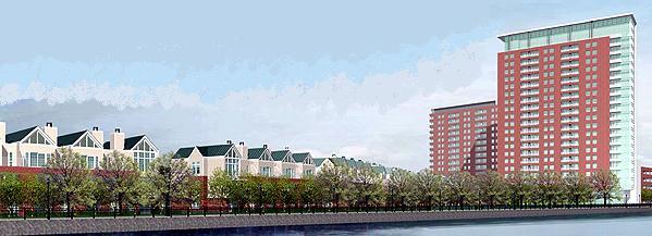
This is a preliminary analysis of the existing design of the River Tower structure, consisting of dead, live, wind, and seismic calculations, along with a lateral load resistance check of the shear wall system. A spot check of one of the typical floor slabs of the structure also appears in this report. Most of my findings were consistent with those design parameters. The lateral load and spot check calculations will require further research and will be more updated in future reports. This is the first submission of this assignment for grading purposes, and an updated resubmission will be posted soon.
View the Executive Summary for Tech1 (51 KB)
View the Full Tech1 Report: Exec. Summary, Paper, and Appendix (5 MB)
View the Paper and Appendix Only (5 MB)
View the Paper Only (520 KB)
Technical Assignment 2
This second technical assignment involves the research of alternate floor systems for the River Tower. Some factors under consideration were system dead weight, constructability and cost, and floor-to-floor depths. My preliminary findings yielded promising results for a composite steel deck/concrete slab floor system and a hollow core slab system. The results of this report will eventually be used to formulate a proposal for the eventual redesign of the current structure in future reports and assignments.
View the Executive Summary for Tech2 (40 KB)
View the Full Tech2 Report: Exec. Summary, Paper, and Appendix (5.33 MB)
View the Appendix Only (5.18 MB)
View the Paper Only (5.26 MB)
Technical Assignment 3
This third technical assignment involves a more detailed analysis of the River Tower; specifically its lateral resistance structural system. The main lateral system for this structure is the reinforced concrete shear walls that are scattered throughout the building. The main shear walls are located around the elevator and stairwell cores, and along the perimeter of the building. This report contains primarily hand calculations, and a more thorough computer analysis will follow in future reports to confirm and in some cases correct what is presented here.
View the Executive Summary for Tech3 (422 KB)
View the Full Tech3 Report: Exec. Summary, Paper, and Appendix (2.16 MB)
View the Appendix Only (2.36 MB)
View the Paper Only (625 KB)