Welcome to Michelle's AE Senior Thesis e-Portfolio
Building Statistics
Building Name:
∙ William W. Wilkins Professional Building
Location:
∙ Columbus, OH 43215
Site:
∙ 285 East State Street
Occupant Name:
∙ Grant/Riverside Methodist Hospitals
Building Function:
∙ Medical Office Building
Building Size:
∙ 111,808 sq. ft.
Number of Stories Above Ground:
∙ 6 stories plus small penthouse/machine room
Project Cost:
∙ $7.4 Million, this includes finance, A/E fees and construction costs.
Construction Duration:
∙ March 1, 2002 - Jan 1, 2003
Project Delivery Method:
∙ Design-Bid-Build
Zoning:
∙ Nothing special
Historical Requirements:
∙ None
Building Code:
∙ Ohio Basic Building Code, 1998 (OBBC)
Project Team:
∙ Owner: State Sixth LLC
∙ Architect:URS
∙ Structural Engineer: URS
∙ MEP Engineers: URS
∙ Plumbing Engineer: URS
∙ Geotechnical Engineer: CTL Engineering, Inc.
∙ Site/Sewer Engineer: Bird & Bull
∙ Elevator Engineer: OTIS
∙ CM/GC/Developer: The Daimler Group
∙ Project Manager: URS
∙ Health Group Designer: URS
∙ Demolition: Darby Creek Excavating, Inc.
∙ Temporary Protection: Paul Peterson Company
∙ Hoist Rental: TNT Equipment
∙ Concrete: Scioto Darby Concrete, Inc.
∙ Precast Concrete: Gate Bluegrass Precast, Inc.
∙ Caissons: Parks Drilling Company
∙ Masonry: Lassel Karst Sons, Inc.
∙ Structural Steel: Ferguson Steel Co.
∙ Fireproofing Contractor: Omni Fireproofing Co.
∙ Fire Protection Contractor: Simplex Grinnell LP
∙ Roofing Contractor: Holland Roofing of Columbus
∙ EIFS: Construction Systems, Inc.
∙ HVAC Contractor: Metro Heating and Air Conditioning
∙ Plumbing Contractor: Diewald & Pope, Inc.
∙ Electrical Contractor: Roehrenbeck Electric, Inc.
Architecture:
This six story building is designed around a central lobby area. The main entrance off Sixth Street opens into a vestibule on the East side of the building which proceeds into the main lobby area. The three elevators and two stairwells are located in the main lobby area. There is a service/delivery entrance located on the West side of the building. The central portion of the building houses the data and electrical rooms, the janitor rooms, and a first floor pump room. The floors are broken down into various medical offices with treatment areas, reception/waiting areas, exam rooms, and doctors’ offices. The first floor is occupied by the kidney dialysis center. The second floor contains a large library as well as areas for the doctors and nurses such as sleep and locker rooms. The third floor is designated for business uses. Located on the fourth floor are some of the exam rooms and offices. More offices are placed on the fifth floor with conference rooms. This floor is also designated for business use. On the sixth floor there are a couple of classrooms designated for education purposes as well as more offices.
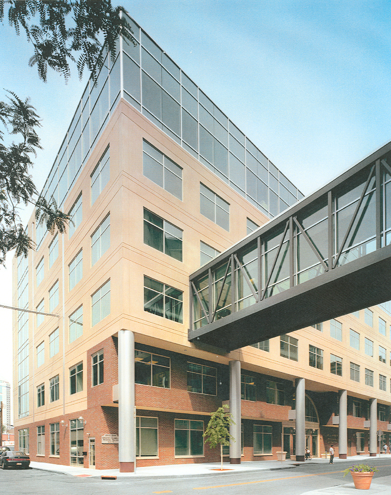
Building Envelope:
East Elevation: This elevation contains the main entrance into the building. Located slightly off center the entrance consists of clear tempered glass double doors with tinted insulated glass on either side. There is a large arch framed in stone above the doors and windows with a bottom row of spandrel glass and more tinted insulated glass above shaped to match the stone arch. There are seven columns approximately 26’-8” tall encased in metal siding supporting the upper levels which overhang creating a covered walkway in front of the building. The underside of this overhang is encased with EIFS. The façade under the overhang consists of brick veneer with two 10’-0” x 7’-4” tinted insulated glass windows spaced evenly in the 30’-9: column lines. The ground floor windows have spandrel glass above and stone lintels below. At this point precast concrete panels were installed. The window pattern started in the brick veneer continues. At an elevation of 69’-8” the façade changes to spandrel glass panels. The window pattern changes slightly from two windows to one 24’-8” window centered on the column line. The Northern end of this elevation is slightly different from the rest. The brick veneer continues to an elevation of 40’. Here the spandrel glass with one large window begins.
West Elevation: This elevation is the most basic and consistent elevation. The ground floor consists of brick veneer with openings for the delivery entrance and two louvers. The rest of the building is precast concrete panels. Beginning at the third floor two 6’-8” x 7’-4” windows per column line are observed continuing to the sixth floor.
North Elevation: From this side the metal sided columns can be observed on the East end. The ground level is brick veneer with four 10’-0” x 7’-4” windows. Three have spandrel glass above and stone lintels below as on the East elevation. The fourth, located on the West end and centered in the column line, has spandrel glass encasing it on three sides and a stone lintel below giving a total length of 19’-4”. This configuration on the West end continues to the roof. On the East end the brick continues to an elevation of 40’ with two 6’-6” x 7’4” windows, one per floor. Spandrel glass spans the rest of the way with one 12’-8” x 7’-0” window per floor. The rest of the elevation is precast concrete panels with metal siding accentuation the column lines. The middle portion has two 10’-0” x 7’-4” windows per floor.
South Elevation: This elevation is very similar to the North. The entire West end of the elevation is the same as the West end on the North elevation. The middle portion is also the same with one exception. The top 17’ is spandrel glass with one 24’-8” window centered on the column line. The East end has this same configuration at the top 17’. The East end is where some major differences arise. The ground floor has a 10’-0” x 8’-0” sliding glass door with spandrel glass above. The second floor on this end is half precast concrete with one window and half brick veneer with one window. Floors 3-5 are the typical precast concrete panels with two 10’-0” x 7’-4” windows.
Penthouse/Machine room: All four sides of the penthouse/machine room are covered in metal siding.
Roofing: The roof is a fairly basic ballasted system. It is comprised of 3” steel decking and rigid insulation covered with a Carlisle rubber EPDM membrane held down with gravel ballast.
Construction:
There are a number of interesting points about the construction of this building. One of the main points is that the building site is almost exactly the same size as the footprint. This fact impacted the design of the building skin. For example, most curtain walls are hung from the outside. On a site neighbored by other buildings and a main road there was no room for the crane to maneuver. This is ultimately why brick is only seen on the lower levels of the building, there was no room for scaffolding. As a result of the smalls site most of the building is precast with punch windows that could be set from the inside. An interesting fact with the precast panels is that there was no place to store them. An arrangement was made with the owner of the building directly behind the Wilkins building. A new parking lot in exchange for the ability to store the panels in the buildings parking lot! Due to the lack of maneuvering room one large crane located on Sixth St. was used to erect the steel. Another crane was brought in to erect the precast panels, this crane moved around the building since the steel was already in place.
The last interesting part about the construction of the Wilkins building is the foundation. As noted in the structural description, the Wilkins building is placed on caissons. Normally a building this size would be placed on pile footings. Previously there had been a building on the site with a basement. When this building was demolished it was simply knocked down into the basement and covered. When the site was purchased it was a parking lot. It would have been far more expensive to excavate out the old building remains and backfill to use pile footings. As a result it was decided to drill through this area and use caissons.
Electrical:
The electric power for the Wilkins building enters through (12) 4” conduits from the Division of Electricity transformer vault. Four of these conduits enter the data room for Time Warner and Ameritech service. The remaining (8) proceed to the electrical room. Located in the electrical room on each floor are 6 panel boards utilizing 480/277V or 208/120V. The first floor also contains (2) 208/120V emergency power panel boards located in the generator room. The generator room also houses a standby natural gas generator, a main circuit breaker and an automatic transfer switch which feeds the emergency panel boards.
The main switchboard feeds the (2) 480/277V panel boards at each floor that service lighting and variable air volume boxes. From there the power is sent to a 480V delta transformer with an output of 208/120V to the remaining (4) panel boards which service the receptacles. The elevators, circulating pump and roof top units are fed directly from the main switchboard. The 20A receptacles are located along the walls with a minimum of one per wall.
Lighting:
The lighting in the Wilkins building is pretty straightforward. The ground lobby/elevator area is illuminated with 6” recessed fluorescent down lights to give a warm inviting atmosphere. The lobby/elevator area at each successive floor retains a little of this feeling with a few down lights but the majority of the light comes from 4’-0” standard fluorescent strip lighting. The 4’-0” strip lighting is also utilized in the data and electrical rooms on each floor.
Lighting in tenant spaces is fairly basic consisting mainly of 2’x4’ recessed fluorescent grid troffer lighting. The ground floor treatment rooms use 2’x2’ recessed fluorescent grid troffer lighting and surface mounted incandescent light fixtures. Exam rooms on the third floor also use surface mounted incandescent lights. Emergency lighting capable of operating for 90 minutes is provided in all corridors, the library, classrooms and large meeting and office areas.
Mechanical:
The primary heating, ventilating and air conditioning (HVAC) system consists of four electric nominal 105 ton variable air volume (VAV) rooftop units. Units one and four supply the fourth through sixth floors while units two and three supply the others. Units one and two supply the South portion of the building; units three and four supply the North portion of the building. Each of the units can supply 28,000cfm with a minimum outdoor air intake of 6,000cfm. The rooftop units are the cooling-only type and have variable frequency drives for volume control. The units have smoke detectors to shut down the units upon smoke detection as well as power exhaust and integral pressure control to maintain proper building pressurization. A small nominal 5 ton heat pump, also located on the roof, serves the elevator machine room. This smaller unit can supply 2,000cfm with a minimum outdoor air intake of 200cfm.
Air is distributed down vertical shafts in high pressure rectangular ductwork. The ductwork transitions to round and flat oval exiting the shafts in a manner to minimize noise. Parallel fan assisted VAV boxes and straight through VAV boxes at each floor provide individual zone control for the majority of the spaces. Boxes at the perimeter and in some interior spaces have electric heating coils to provide the source of heat for the facility. Series fan assisted boxes are employed in the lobby and entry ways. Single duct boxes are used for electrical and communication closets. 2’x2’ architectural ceiling diffusers are used in the majority of spaces. The fan assisted boxes with heating coils are capable of providing after hours heating without starting the rooftop air handling units. A plenum return system is used to minimize the amount of return air ductwork. All fan assisted VAV boxes have smoke detectors to comply with the latest code changes.
The majority of the HVAC functions are controlled through a standard direct digital control (DDC) system which has minimal energy management functions. A portable operator’s terminal (POT) enables programming changes to be made at DDC control panels.
Structural:
The structural system for the Wilkins building begins with caissons drilled 25’-2”, on average, to rest on soil with a bearing value of 16,000psf. On each caisson is a pier. Framing into the piers are grade beams that range in size from 12”x32” to 24”x32”. The ground slab is 4” concrete reinforced with 6x6-W1.4xW1.4 welded wire fabric (WWF) sitting on 6” porous fill. Floors 2-6 consist of a 3 ½” concrete slab on 2” 18ga composite steel deck welded to the support steel. These slabs are reinforced with 6x6-W2.1xW2.1 WWF. A typical bay is 30’-9”x32’-4” split into three equal spans. Floor framing generally consist of a W16x31 beam connected compositely to the floor slab with (17) ¾”ø, 4 ½” headed shear studs. Beams frame into a W24x55 girder using (35) ¾” ø, 4 ½” headed shear stud. Roof framing typically utilizes a W16x31 or W16x26 beam framing into a W24x55, W21x50, or W21x44 interior girder or a W18x3 or W16x31 exterior girder. Columns are ASTM 992 Grade 50 rolled W12 steel shapes.
Lateral bracing, in the form of concentric braced tube frames, is located on the North and South faces of the building in the West end bay. Additionally there are two braced frames spanning North-South and one spanning East-West in the stairwell, elevator shaft area.
Fire Protection:
The Wilkins building is equipped with an automatic New Wet Pipe sprinkler system. The building is broken into two different occupancy groups per NFPA chapter 13. The majority of the building is in the light hazard occupancy requiring a density of 0.10GPM per sq.ft. over the area with a maximum of 225 sq. ft. per head. The electrical, data, pump, storage/records, utility/maintenance and emergency generator rooms are classified as ordinary hazard group 1. This requires a density of 0.15GPM per sq. ft. and a maximum of 130 sq. ft. per head.
Spray on fireproofing was used on all steel. Beams framing stairwells, elevators and/or shaft openings as well as columns supporting floors at shaft enclosures have a 2hour rating. Everything else, including roof and floor construction, has a 1hour rating.
Transportation:
There are three electric geared traction passenger elevators in the William W. Wilkins building that service all six floors. Two of the elevators are Otis model GEM3535. These cars can carry 3500lbs @ 350fpm in their 6’-8”x5’-5” interiors. The third car is an Otis model GEM4535H. This has a capacity of 4500lbs @ 350fpm with a slightly larger interior of 5’-8”x7’-11”. Operating these elevators are a variable voltage variable frequency drive and an alternating current motor connected to the geared traction drive sheave. The hoisting ropes connect to the car hitch, wrap around the grooved drive sheave and finally connect to the counterweight; the ends terminate at hitches in the machine room.
There are several safety features built into these elevators. First there is a governor rope connecting the governor and tension sheaves. If this rope breaks or the car speeds downwards the car safety activates which applies friction to stop the car. At the bottom of the elevator pit is a buffer to absorb the shock from a counterweight or car. Finally there are limit switches mounted on the guardrails. If these are activated, power is cut and the hoist brake is applied.
Special Systems:
The Wilkins building has a centrally monitored card access system. In addition there is a nurse call system and code blue system installed on clinical floors.